The CAN (Controller Area Network) protocol is widely used for reliable device communication in automotive and industrial applications. In this project, we will build a simple CAN Bus Simulator with MCP2515 and Arduino, also an MCP2551 CAN transceiver will be used. This setup allows us to read CAN messages and display the data using serial communication.
⚠️Disclaimer:
Working with electricity involves serious risk. Ensure you have the necessary skills and take proper safety precautions before attempting any electrical projects. Proceed at your own risk — the author assumes no responsibility for any damage, injury, or issues resulting from the use or misuse of the information provided.
All content on this website is original and protected by copyright. Please do not copy or reproduce content without permission. While most of the resources shared here are open-source and freely accessible for your learning and benefit, your respect for our intellectual effort is appreciated.
If you find our tutorials helpful, consider supporting us by purchasing related materials or sharing our work — it helps keep the content flowing.
Need help or have questions? Leave a comment below — the author is always happy to assist!
Table of Contents
What is CAN Bus?
The Controller Area Network (CAN) bus is a robust communication protocol developed by Bosch in the 1980s. It is designed for efficient and fault-tolerant real-time data exchange between multiple devices (or nodes). Widely used in automotive and industrial applications, the CAN bus allows microcontrollers and devices to communicate with each other without needing a host computer.
Key Features of CAN Bus:
- Reliable Communication: Error detection mechanisms like CRC ensure data integrity.
- Multi-Master Protocol: Any node can initiate communication, allowing for flexibility.
- Efficient Use of Bandwidth: Uses arbitration to prioritize messages and avoid collisions.
- Robustness: Designed to work in noisy environments with differential signaling (CANH and CANL).
- Speed: Supports data rates of up to 1 Mbps in standard configurations.
CAN Bus Configuration:
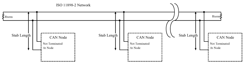
- Physical Layer:
- Two wires: CANH (High) and CANL (Low).
- Termination resistors (120 Ω) at both ends to prevent signal reflection.
- Frame Structure:
- Identifier (ID): Identifies the priority and content of the message.
- DLC (Data Length Code): Indicates the size of the data payload (0 to 8 bytes).
- Data: Actual information being transmitted (e.g., speed, temperature).
- CRC (Cyclic Redundancy Check): Ensures data integrity.
- Types of Messages:
- Data Frame: Contains data to be transmitted.
- Remote Frame: Requests data from other nodes.
- Error Frame: Indicates transmission errors.
- Overload Frame: Signals have a delay in transmission due to busy conditions.
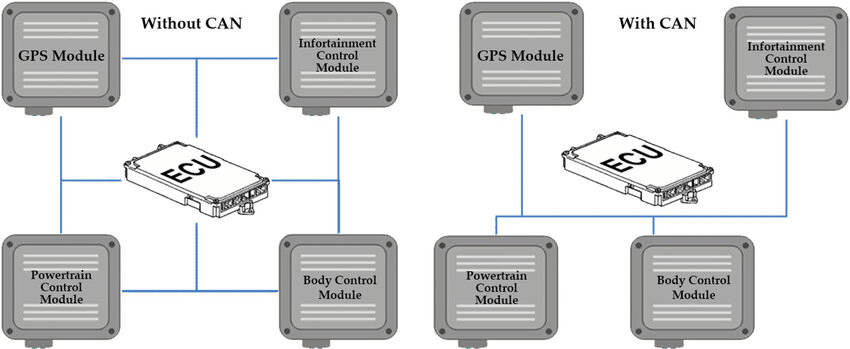
Uses of CAN Bus:
- Automotive Applications:
- Engine control, braking systems (ABS), airbag systems, and infotainment.
- Industrial Automation:
- Communication between sensors, actuators, and controllers in factories.
- Medical Devices:
- Data exchange in advanced medical equipment like CT scanners.
- Aerospace:
- Onboard communication in aircraft systems.
- Robotics:
- Ensures coordinated communication in robotic arms and autonomous vehicles.
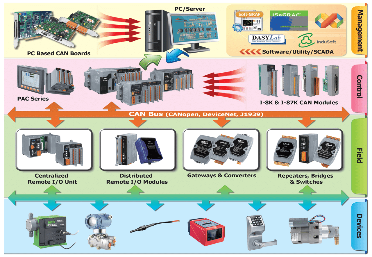
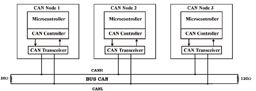
Diagram of a CAN Bus System:
The following image shows a basic CAN bus topology with multiple nodes connected via CANH and CANL lines. Termination resistors are added at both ends of the bus for signal integrity.
Designing CAN Bus Simulator :
We need an Arduino (uno or nano, I used UNO here). MCP2515 CAN Controller and MCP2551 CAN Transceiver. Few passive components. And that’s it.
Circuit Diagram:
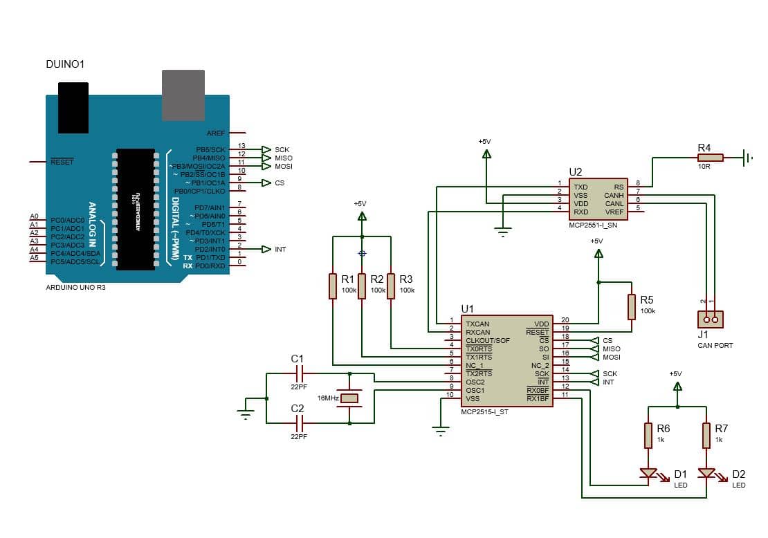
This diagram illustrates the setup for a CAN bus simulator using an Arduino Uno, MCP2515 CAN controller, and MCP2551 CAN transceiver. The MCP2515, connected to the Arduino via SPI (pins 10 for CS, 11 for MOSI, 12 for MISO, and 13 for SCK), manages CAN data processing. The MCP2551 acts as the transceiver, interfacing the CAN controller with the physical CAN bus via CANH and CANL lines.
Termination resistors (R4 and R5) ensure signal integrity on the bus. A 16 MHz crystal oscillator (with capacitors C1 and C2) provides the clock for the MCP2515. LEDs (D1 and D2) with 1 kΩ resistors (R6 and R7) can be used as indicators for transmission or activity. The circuit is powered by a 5V supply, and additional pull-up resistors (R1, R2, and R3) stabilize the system. The CAN port (J1) connects to external devices for communication testing.
Code:
#include <SPI.h>
#include <mcp2515.h>

struct can_frame canMsg;
MCP2515 mcp2515(9);


void setup() {
  Serial.begin(115200);
  SPI.begin();

  mcp2515.reset();
  mcp2515.setBitrate(CAN_125KBPS);
  mcp2515.setNormalMode();

  Serial.println("------- CAN Read ----------");
  Serial.println("ID  DLC   DATA");
}

void loop() {

  if (mcp2515.readMessage(&canMsg) == MCP2515::ERROR_OK)
  {

    Serial.print(canMsg.can_id, HEX); // print ID
    Serial.print(": ");
    Serial.print(canMsg.can_dlc, HEX); // print DLC
    Serial.print(" ");

    for (int i = 0; i<canMsg.can_dlc; i++)  {  // print the data

      Serial.print(canMsg.data[i],DEC);
      Serial.print(" ");

    }

    Serial.println();
  }

}
Code Explanation:
void setup() {
  Serial.begin(115200);
  SPI.begin();

  mcp2515.reset();
  mcp2515.setBitrate(CAN_125KBPS);
  mcp2515.setNormalMode();

  Serial.println("------- CAN Read ----------");
  Serial.println("ID  DLC   DATA");
}
Serial.begin(115200): Initializes serial communication with a baud rate of 115200 for printing debug messages.SPI.begin(): Initializes the SPI communication between the Arduino and the MCP2515 module.mcp2515.reset(): Resets the MCP2515 CAN controller to its default
state.mcp2515.setBitrate(CAN_125KBPS): Sets the CAN bus bitrate to 125 kbps. This can be adjusted based on the actual CAN bus speed you want to use.mcp2515.setNormalMode(): Sets the MCP2515 to normal mode, allowing it to send and receive messages. The two Serial.println() statements print an initial message to the serial monitor, indicating the start of the CAN message read operation.
void loop() {

  if (mcp2515.readMessage(&canMsg) == MCP2515::ERROR_OK)
  {

    Serial.print(canMsg.can_id, HEX); // print ID
    Serial.print(": ");
    Serial.print(canMsg.can_dlc, HEX); // print DLC
    Serial.print(" ");

    for (int i = 0; i<canMsg.can_dlc; i++)  {  // print the data

      Serial.print(canMsg.data[i],DEC);
      Serial.print(" ");
    }

    Serial.println();
  }
}
mcp2515.readMessage(&canMsg): Reads a CAN message from the MCP2515 and stores it in thecanMsgstructure. It returnsMCP2515::ERROR_OKif the message is read successfully.- If a message is successfully read, it prints the following details:
canMsg.can_id: The CAN message ID in hexadecimal format.canMsg.can_dlc: The Data Length Code (DLC) indicates the number of data bytes in the message and is printed in hexadecimal.canMsg.data[]: The actual data of the CAN message is printed byte by byte in decimal format.
- After each message is printed, a newline (
Serial.println()) is sent to the serial monitor.
Summary:
The program reads messages from the CAN bus using the MCP2515 controller and displays the message ID, DLC, and the actual data of the message in the serial monitor. The CAN communication speed is set to 125 kbps, and the MCP2515 operates normally to send and receive messages. The program runs in an infinite loop, constantly reading and printing incoming CAN messages.
Ads:
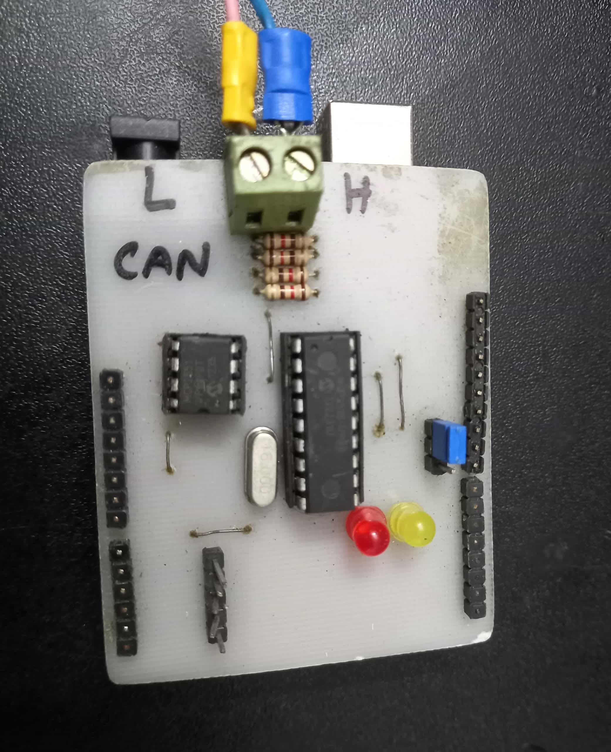
My Can Bus Simulator:
Once the circuit is in the real CAN bus line. It can read the data from the line and print it with details on the serial terminal. I made the simulator in this small PCB while testing and working in the CAN line. But unfortunately, I forgot to capture the images while working. But the module is here:
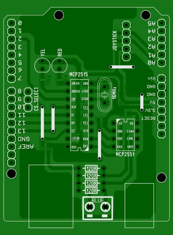
PCB:
Conclusion:
I hope this article will be helpful when you need something like this. The simulator itself is really useful for testing when a real CAN scanner is not available. I used it for a field project, and later, I bought a real CAN simulator. But until I got that, this small kit helped me a lot.
Liked this article? Subscribe to our newsletter:
or,
Visit LabProjectsBD.com for more inspiring projects and tutorials.
Thank you!
Read more:


0 Comments