Measuring high voltage AC is not safe just with a resistor voltage divider. Or sometimes, we can not connect one terminal to the GND of the measuring circuit. Sometimes, we need to measure a floating high voltage. In this article, we are going to learn how to do that floating high voltage measurement using Op-Amp.
⚠️Disclaimer:
Working with electricity involves serious risk. Ensure you have the necessary skills and take proper safety precautions before attempting any electrical projects. Proceed at your own risk — the author assumes no responsibility for any damage, injury, or issues resulting from the use or misuse of the information provided.
All content on this website is original and protected by copyright. Please do not copy or reproduce content without permission. While most of the resources shared here are open-source and freely accessible for your learning and benefit, your respect for our intellectual effort is appreciated.
If you find our tutorials helpful, consider supporting us by purchasing related materials or sharing our work — it helps keep the content flowing.
Need help or have questions? Leave a comment below — the author is always happy to assist!
Table of Contents
What is floating voltage?
In most cases, one terminal of the measuring point is connected to the GND of the measuring circuit. But sometimes, we can not do that. Like if you wish to measure 220V AC using your MCU circuit, you should not connect the Neutral terminal to the GND of your MCU circuit to keep it safe. In this case, you need to keep that Neutral terminal floating.
That means, the floating voltage means, the voltage difference between two points of which are not connected to VCC nor GND.
How to measure floating voltage?
There are different ways to measure this floating voltage. You can use a transformer, Op-Amp, or even optocouplers.
Using a transformer will make it safe and isolated but it will increase the size and weight of measuring circuitry. On the other hand, Op-Amp is cheap as well as small in size. Also, provide good linearity. But Op-couplers can give you the status of voltage presence but can not maintain good linearity.

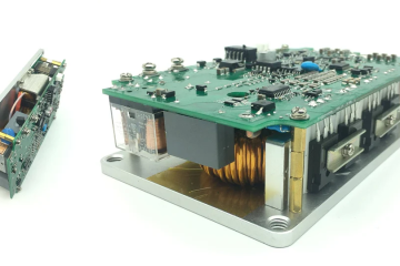
Transformer 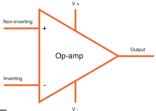
Op-Amp 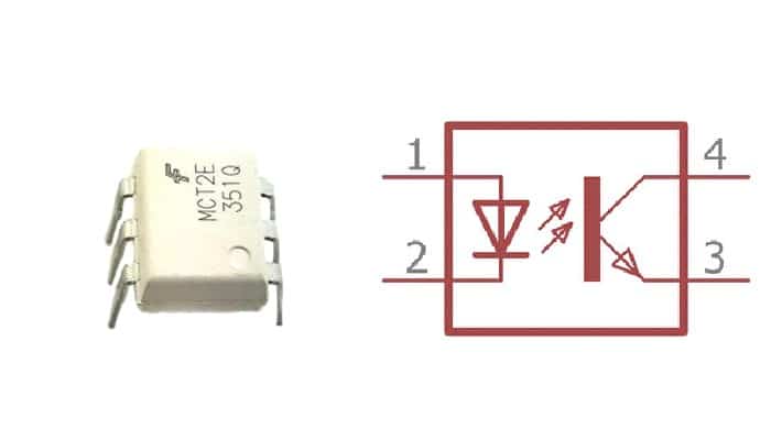
Opto-Coupler
Circuit diagram using Op-Amp
Here in this article, we’ll make our circuit with Op-Amp to measure high voltage.


As you can see, we used multiple resistors in series with a high voltage source. R1, R3, R4, R5 are connected in series. Using multiple resistors provide good isolation to AC high voltage. Also, heat due to power loss is significantly reduced.
In this circuit, you can see that we used a voltage reference of 2.5V which is feed to the non-inverting terminal through the R10 resistor. Here in this circuit, R9 is working as our feedback resistor.
The gain of this circuit is:
Gain = R9/(R2+R6+R7+R8);
Note that, R1+R3+R4+R5 must be equal to R2+R6+R7+R8. Or distortion in output will arise.
The voltage reference should be selected carefully to obtain the full range of voltage. Note that, the output null point is 2.5V. That means if there is no input voltage, there will be a 2.5V DC at the output terminal.
Simulation result:
Here is the simulation result:
As you can see the result in the simulation. But I’ve been using this circuit in many products for many years. It works fine. You can easily implement this circuit in your circuit too.
I hope you learned something and enjoyed this project. If you need any help, I’m Mithun here for that. Thank you, Enjoy!
Liked this article? Subscribe to our newsletter:
or,
Visit LabProjectsBD.com for more inspiring projects and tutorials.
Thank you!
Check this out: 5 coolest multimeters you can buy


8 Comments
enrique · 04/11/2020 at 3:15 am
Excellent explanation as always your work is very good thanks
Mithun K. Das · 04/11/2020 at 6:21 am
Thanks
Mihail · 13/07/2022 at 12:03 am
as a result, the resistance R9 still combines the power part circuit and the MCU part. You can also do without an operational amplifier if you use the same number of resistances, as you write in this article
MKDas · 13/07/2022 at 11:18 am
R9 is for Op-Amp mode setup. Use this way to maintain a safety.
nouman · 15/03/2023 at 2:19 am
sir kindly upload the arduino code ?
thanks
MKDas · 15/03/2023 at 11:59 am
read similar articles in this blog.
Patrick · 07/04/2023 at 4:53 am
I’d like to use this but I’m a bit apprehensive. I tried to model it using LTspice and it doesnt seem to work. Is it safe for the microcontroller, is it stable? Why is spice giving me strange results? Anyone have any ideas.
MKDas · 07/04/2023 at 8:42 pm
in that case you must ensure the GND is same to MCU & Op-Amp