In this article, we are going to learn about the solar charge controller. There are different types of solar charge controllers in the market. All these have different working principles. But the basic principle is the same. In this article, we will learn the basic principle of the solar charge controller and a few details with a circuit diagram. I hope this article will be helpful to you. So let’s start our Solar Charge Controller circuit.
⚠️Disclaimer:
Working with electricity involves serious risk. Ensure you have the necessary skills and take proper safety precautions before attempting any electrical projects. Proceed at your own risk — the author assumes no responsibility for any damage, injury, or issues resulting from the use or misuse of the information provided.
All content on this website is original and protected by copyright. Please do not copy or reproduce content without permission. While most of the resources shared here are open-source and freely accessible for your learning and benefit, your respect for our intellectual effort is appreciated.
If you find our tutorials helpful, consider supporting us by purchasing related materials or sharing our work — it helps keep the content flowing.
Need help or have questions? Leave a comment below — the author is always happy to assist!
Table of Contents
What is a solar charge controller?
In a solar power system, energy is harvested from sunlight and stored in a battery; then, the battery gives us power backup when required. This is very simple. But the problem is, that each battery has a limit of taking charge and being discharged. That is why we need a controller to control both the charge and discharge limit. Otherwise, the battery will be damaged.

Working principle of Solar Charge Controller:
A charge controller has a basic operation of sensing and switching the electrical connection between the solar panel, battery, and load. Although this mechanism differs from controller to controller (we’ll discuss this later) you can say this is some kind of switch-like relay switch. There is a switch between the solar panel and the battery and another switch between the battery and to load. Besides, it senses the battery voltage and panel presence. That’s it in a very simple way. Check this block diagram of the Solar Charge Controller circuit.

Here SW is the switch. This switch can be electronic or relay type depending on the controller situation. But let’s guess it is as simple as a switch. Now, two voltages need to be sensed, that is why two voltage sensors are required. Although for the advanced charge controller, there are some other functions for the basic one, this is all we need to have.
So how does the charge controller work?
First of all, the controller senses the battery condition. If it needs to be charged, it turns on the switch between the solar panel and the battery. Afterward, if the battery is fully charged the controller turns this charging switch (between solar panel and battery) off. Besides, the controller keeps the switch (between the battery and load) on and if the battery is discharged below a certain level, it turns this load switch off. This is how the charge controller works.
Sometimes in a large charge controller, the load switch part is not available. Because in large power systems, other devices like inverters are used which already have their own discharge protection. But in small charge controllers, loads are directly connected with the charge controller.


Types of solar charge controllers:
Based on operation principles, solar charge controllers are three basic types. These are
- ON/OFF Charge controller
- PWM Charge controller
- MPPT charge controller
ON/OFF Charge controller:
The on/Off charge controller is the most basic and easy one. It simply uses a simple switch as the block diagram explained earlier. Usually, MOSFETs are used as the switch. As there is no extra current control mechanism in the ON/OFF charge controller it can not manage the battery charging capacity. That is why this type of charge controller is not so efficient.
| Pros | Cons |
| Simple circuit, less maintenance | Poor battery management |
| Lowest in price comparing other controllers | Poor charging efficiency |
PWM Charge Controller:
In the PWM charge controller, PWM (Pulse Width Modulation) is used to control the charging current. This is an extra feature compared with the ON/OFF Charge controller. To fully utilize the charging capacity of a battery the battery should be charged in three steps. Bulk, Absorption, and float. Only with PWM control, this 3-step charging control is possible. Which improves the battery charging efficiency as well as improves backup time with battery life.
| Pros | Cons |
| Improved battery charging ensures longer battery life | Low power harvesting capacity than MPPT |
| Low price | Moderate charging efficiency |
MPPT Charge Controller:
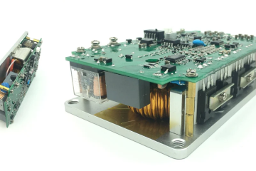
In the MPPT charge controller, the DC/DC converter (SMPS) is used. Usually, a Buck converter is commonly used. The switch-mode power supply is much more efficient in power conversion. That is why it is more efficient in switching. Besides, the MPPT charge controller uses MPPT algorithms to get the maximum power from a solar panel. I’ve posted an article on this. Please check this article here. I’ve explained detailed information about MPPT in that article. That is why I’m not discussing the circuit of the MPPT charge controller here.
| Pros | Cons |
| Maximum power harvesting from solar panel | Complex circuitry |
| Excellent battery and load management | High Price |
In this article, we will discuss the first two types of solar charge controllers.
Circuit diagrams:
There is no difference other than the switching signal between an ON/OFF and PWM charge controller. The common circuit diagram is like this; where the current flow direction is shown. Based on the current flow, MOSFETs are used in different positions.

Now, keep a note that most of the MOSFETs are voltage biased and the gate to source voltage Vgs is 10V for full contact. That is why, to switch these MOSFETs properly, we need to use an optocoupler. Opto-coupler works like a voltage shifter here as well as an isolator too.
ON/OFF type Solar Charge Controller circuit:

And PWM type Solar Charge Controller circuit:

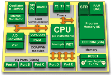
The primary distinction between these circuits is the method of charging control. This can be achieved using a basic on/off switching mechanism or a more advanced PWM approach. Employing a microcontroller offers substantial benefits over analog designs, simplifying the implementation and providing greater design flexibility. Although op-amp circuits offer a less complex alternative if microcontroller programming presents a challenge, microcontrollers are generally preferred due to their versatility and broader range of control options.
Having reviewed the fundamental circuit, you should now grasp the basic operating principles. To achieve comprehensive system control, including voltage and presence sensing, the circuit can be further refined as shown below:

Charging is controlled by the circuitry on the left, and load/discharge management is handled by the circuitry on the right. An L78L05 voltage regulator provides a stable 5V supply.
Basic operation:


Analog circuits need lots of tuning to get an optimum result. Also, not all the components are ideal. A small tolerance of the resistors can displace the working point. That is why you need to tune the circuit properly. But as simple Op-Amps are very cheap in the market, the total cost is pretty low.
On the other hand, using a small microcontroller makes this very easy to control and tune. If we convert this analog circuit into a microcontroller-based circuit, then it will be like this:
If replaced by a microcontroller:

This demonstrates how an 8-pin microcontroller can significantly simplify control circuitry compared to traditional analog methods. The digital approach offers greater flexibility in managing charging and discharging parameters through simple software implementations. This solution is also more cost-effective than dedicated MPPT or PWM charge controllers. It’s worth noting that the microcontroller can also be programmed to generate PWM signals directly.
You may read this: PWM Solar Charge Controller with PIC12F675
Coding:
/*******************************************************************************
Program for, Simple ON/OFF charge controller
Program Written by_ Engr. Mithun K. Das; [email protected]
MCU:PIC12F675; X-Tal: 4MHz(internal). Compiler: mikroC pro for PIC v7.6.0
Date: 28-03-2021; © labprojectsbd.com
*******************************************************************************/
#define  charge_pin     GP0_bit
#define  load_pin       GP4_bit
#define  ch_led         GP5_bit
#define  ld_led         GP2_bit
#define  solar_sense    GP3_bit

unsigned int battery=0;
int i=0;
bit charge;
bit load;


void main()
{
  TRISIO = 0b00001010;//set I/O ; 1=input, 0=output
  GPIO = 0x00;
  CMCON = 0x07;//comparator off
  ANSEL = 0b00000010;//AN1 analog only
  ADCON0 = 0x05;//AN1 channel selected
  while(1)
  {
     //read battery voltage
     battery=0;//clear previous data
     for(i=0;i<20;i++)
     {
        battery += ADC_Read(1)*27/100; // *5/1023*(10+2.2)/2.2*10*calibration
        Delay_ms(10);//keep a delay for smooth measurement
     }
     battery/=20; // make an average result from 20 samples.

     //Note: here rather than taking floating point variable, unsigned int
     //is used and while calculating, eliminated fractions to reduce further
     //RAM & ROM use.


     //charge control
     if(solar_sense)
     {
        if(battery>145)charge = 1;//charge high cut
        if(battery<132)charge = 0;//charge reconnect

        if(charge)//full charge condition
        {
           ch_led = 1; //full charge indication
           charge_pin = 0;//keep off charging mosfet
        }
        else
        {
           ch_led = ~ch_led; // Toggle ch_led for charging indication
           charge_pin = 1;//keep on charging mosfet
        }
     }
     else
     {
        charge_pin = 0; //do not charge
        ch_led = 0; //indicator off
        charge = 0;//reset charge
     }


     //load control
     if(battery>126)load = 1;//load reconnect
     if(battery<116)load = 0;//load disconnect

     if(load)
     {
        load_pin = 1; //load MOSFET on
        ld_led = 1;//LOAD on indication
     }
     else
     {
        load_pin = 0; //load MOSFET off
        ld_led=~ld_led;//LOAD off indication
     }


  }//end of while(1)
}//end of void main


//End
Code explanation:
This code implements a basic charge controller for a solar power system using a PIC12F675 microcontroller. Here’s a breakdown of its functionality:
1. Pin Definitions and Initialization:
- Defines symbolic names for various I/O pins:
charge_pin: Controls the charging MOSFET (likely connected to the gate).load_pin: Controls the load MOSFET (likely connected to the gate).ch_led: Charge indicator LED.ld_led: Load indicator LED.solar_sense: Indicates presence of solar voltage (connected to a voltage divider or comparator output).
- Sets up I/O pins:
TRISIO: Configures specific pins as input (1) or output (0).GPIO: Sets initial state of all output pins to 0.CMCON: Disables the internal comparator.ANSEL: Sets only AN1 (GP3) as an analog input pin.ADCON0: Selects AN1 (channel 1) for the ADC conversion.
2. Main Loop:
- Battery Voltage Reading:
batteryvariable is initialized to 0 for each iteration.- A loop reads the ADC value from channel 1 (AN1) 20 times and accumulates the results in
battery. - A delay (
Delay_ms(10)) ensures a stable reading between samples. - The final
batteryvalue is an average of the 20 readings. - Note: The code uses integer calculations to avoid using floating-point numbers, saving memory.
- Charge Control:
- If
solar_senseis high (indicating solar voltage presence):chargebit is set to 1 ifbatteryis above 145 (high voltage cut-off for charging).chargebit is set to 0 ifbatteryfalls below 132 (reconnect charging).
- Based on the
chargebit:- If
chargeis high (battery fully charged):ch_ledis turned on to indicate full charge.charge_pinis set low to turn off the charging MOSFET.
- Otherwise (battery needs charging):
ch_ledis toggled for a blinking charging indication.charge_pinis set high to turn on the charging MOSFET.
- If
- If
solar_senseis low (no solar voltage):charge_pinis set low to stop charging.ch_ledis turned off.chargebit is reset to 0.
- If
- Load Control:
- If
batteryis above 126, theloadbit is set to 1 (reconnect load). - If
batteryfalls below 116, theloadbit is set to 0 (disconnect load). - Based on the
loadbit:- If
loadis high (load can be connected):load_pinis set high to turn on the load MOSFET.ld_ledis turned on to indicate load connection.
- Otherwise (battery voltage too low for load):
load_pinis set low to turn off the load MOSFET.ld_ledis toggled for a blinking load disconnect indication.
- If
- If
This code provides a basic control strategy for charging and load management based on battery voltage and solar presence. However, it lacks some features for a robust system:
- No Hysteresis: The thresholds for charging on/off and load on/off are very close, leading to rapid switching near the trigger points. Implementing hysteresis (a small voltage difference between the on and off thresholds) would prevent this.
- No Over-current Protection: The code doesn’t limit the charging current or load current. This could damage the battery or system components if exceeded.
- No Temperature Compensation: Battery voltage varies with temperature. The code doesn’t compensate for this, which could lead to inaccurate charging and load control.
For a more reliable system, consider adding these features and using a more sophisticated control algorithm.
The code is very simple for the ON/OFF charge controller. If you have a mikroC compiler, you can build the hex file, but if you do not have any, you can download this hex from here.
Conclusion:
To make a PWM charge controller, we need to change only the charging signal. In that case, you can code yourself to add software PWM. I’ll try to publish the PWM one in my next article. Please subscribe and stay with this blog. So that you can get the updated project notification.


I hope this project was helpful to you. If you make one for yourself, it will be a great pleasure for me. Anywhere you need help, let me know. Please share this project and subscribe to my blog. Thank you.
Don’t forget to subscribe if you want to get more useful articles.
Liked this article? Subscribe to our newsletter:
or,
Visit LabProjectsBD.com for more inspiring projects and tutorials.
Thank you!
Check this out: 5 coolest multimeters you can buy


Ads:

66 Comments
Joy · 28/03/2021 at 5:37 pm
Nice ..sir.
Asimiyu · 29/03/2021 at 2:39 am
Thank you sir for the new project updated. May God Almighty Allah continue to enrich you more in knowledge, with strength, money, long life and prosperity. I have gained more knowledge from your blogs this morning, and it has been added to what I had learned and being doing. So thank you.
However, sir. The question is that, (1) at the solar panel voltage side, what is the range of the solar Voltages that can be connected, since MOSFET’s gate needs at least 10volts (2) I can see from the programs you developed for ON/OFF (codes), you have used channel (1) or (AN1) for battery sensing only, I was expecting you would use channel (0) for solar sensing too but you have used digital sensing. (i.e if(solar_charge)), so please, Can the microcontroller sense any signal below +5VDC as digital signal ? Because, I was studying the circuit, if the resistors you have used can divide or limit the Voltage to +5V sensing by microcontroller digital pins.
Mithun K. Das · 29/03/2021 at 8:03 am
The solar voltage depends on the battery voltage. This design is for 12V system. But can be used for 24V system with increased heatsink.
issue 1: for 12V PV max is 22V.
issue 2: Digital pin can sense anything over 2.5V as digital 1. As this pin GP3 can be used only as input, so we can use this facility to sense the solar. Otherwise, this pin can’t be used as output or need to be left unused.
Asimiyu · 29/03/2021 at 7:15 am
Secondly, please. Can this circuit be remodified by replacing solar panel with rectified voltage through stepdown transformer to charge battery?, ( That converted to automatic battery charger).
Mithun K. Das · 29/03/2021 at 8:04 am
The transformer can be used if overloading is monitored properly. Otherwise the transformer will be burnt.
Asimiyu · 29/03/2021 at 9:54 am
Thank you sir. It is cleared.
Seun · 09/07/2021 at 6:16 pm
Well done Sir, for efforts put into this. I have some questions.
1. What is the benefit of the optocoupler?
As there are circuit using opamps only.
2. The LED bulb for the charging will always be on even when sun is no more, how can it off at night.
3. If I want to do for 48v system, what are the modifications to do?
4. What is the function of the voltage regulation?
Please how can I incorporate fast 5v output to charge phones, I have tried 7805s in parallel.
Thanks Das
MKDas · 10/07/2021 at 1:36 am
1 >> Isolation is the main point. Then voltage shifting to a higher level.
2 >> In that case, two options. a. driving LED with solar supply but triggering by MCU through a transistor. b. sensing solar voltage and let MCU decide what to do.
3 >> You’ll need two voltage regulators. One for 12V for MOSFET Gate another is 5V for MCU.
4 >> Supplying a constant voltage to its loads. For Cellphone charger you can try MC34063A based 5V SMPS from this link: MPPT Solar Charge Controller.
& Thanks for your comment.
Seun · 13/07/2021 at 2:36 am
Please Sir, can I use either p- or n- channel MOSFETs, because I can see you used p- channel along the negative line.
MKDas · 13/07/2021 at 4:20 pm
Which one did you found P-Channel? All N-Channel MOSFETs were used here.
Seun · 12/08/2021 at 3:58 am
Sir, please for 48v system, for the load section, how can I made it for 12v loads. Thanks
MKDas · 12/08/2021 at 11:47 am
If you use a 48V system and want to drive loads of 12V then make a buck converter that can convert 48V into 12V. Then integrate with your 48V system.
Seun · 14/08/2021 at 10:07 pm
Thanks, please do you have any simple buck converter circuit
MKDas · 15/08/2021 at 11:53 am
Welcome. Yes, please search ‘Buck’ on the top.
Lakshman · 30/07/2021 at 10:19 am
Dear Sir,
Have nice day ,
My wishes for your help and support to sharing your knowledge
MKDas · 30/07/2021 at 2:12 pm
Thanks.
Selina Atalifo · 28/10/2021 at 6:14 am
Sir, if you replace the pic12f675 with pic 16f877 microcontroller,will it affect/change the circuit?
Lab Projects BD · 28/10/2021 at 3:19 pm
Only in code declaration of I/O and some other settings. But why do you need to use a cannon to kill a mosquito?
Bob · 29/11/2021 at 4:48 pm
Cannot get PC817 opto couplers, can I use 4N35, I have quite a few of these?
D1 in your schematic, how many 1N5408’s must be in parallel, as you indicate with an “X”
I have nice fat diode of 20amps to use here.
Lab Projects BD · 30/11/2021 at 10:47 am
You can use 4N35. Each Diode 1N5408 can handle 3A. So select qty of diodes depending on your current keeping some safety factor.
Anthony Bosun Osibajo · 30/12/2021 at 10:02 pm
Thanks so much for this. Please i am working on using MPPT to charge batteries ranging from 48-96VDC i will be glad to have your super with the circuitry .
MKDas · 01/01/2022 at 10:39 am
Check this one: https://labprojectsbd.com/2020/04/22/mppt-solar-charge-controller-with-synchronous-buck-converter-with-smps-mobile-charger/
Azim Uddin · 27/05/2022 at 11:42 am
MicroC program gulo ki arduino diye pic microcontroller e upload deya jabe? Process ta jodi janaten pls. Thanks.
MKDas · 27/05/2022 at 2:25 pm
No. You have to use mikroC
Noshin · 18/09/2022 at 10:42 pm
Sir, i have few questions.
1. What will be the input for 12v battery charger
2. If i get 9v from solar and want to charge two 3.7v Lithium-ion battery what will be the Changes in the circuit.
3. How can i understand that my circuit is running in simulation software? When i simulate it i couldn’t see or understand if the circuit is charging or discharging.
MKDas · 20/09/2022 at 10:56 am
1. BAT1
2. It will damage the battery
3. Put test points or meters to investigate.
Aftaqri · 21/01/2023 at 9:28 pm
After 5 seconds of solar sense I want to turn on the charge mosfet. Sir can you help me please.
MKDas · 22/01/2023 at 12:39 pm
use delay(xxx)
Aftaqri · 22/01/2023 at 5:23 pm
if(solar_sense)
{
if(battery>146)charge = 1;//charge high cut
if(battery<128)charge = 0;//charge reconnect
if(charge)//full charge condition
{
ch_led = 1; //full charge indication
charge_pin = 0;//keep off charging mosfet
}
else
{
l —————————————————————————————————–
l ch_led = ~ch_led; // Toggle ch_led for charging indication l
l Delay_ms(5000); l
l charge_pin = 1; //keep on charging mosfet l
——————————————————————————————————-
}
}
——————————————————————————————————————————–
Sir" Charge Led Billing Works Slowly. Please help me Sir
MKDas · 23/01/2023 at 11:41 am
yes, its ok. Test it.
Aftaqri · 23/01/2023 at 1:01 pm
Yes, I tried it but Charge Led Billing Works Slowly.
I want.
(1) When the solar sense is on, the charge LED will blink five times with 1000ms delay.
(2) Charge LED After five times blink It will start blink again for 250ms. and
Charge Mosfet will on.
Hope you solve my problem.
Please help me Sir.
MKDas · 23/01/2023 at 2:27 pm
use for loop
Aftaqri · 24/01/2023 at 3:09 pm
I use delay.
No for loop is needed.
Yes working is fine.
Thanks Sir.
Lino · 20/06/2023 at 4:46 pm
Well done.
These microchip PIC16F877A & PIC12F675 are not available right now. Would you please advise which one I can use to build a cheaper prototyping of the Solar Charging system 50W 17.8V and battery 12V using MPPT
MKDas · 02/07/2023 at 7:31 pm
use similar one, then match the settings registers.
mt · 22/04/2024 at 6:00 pm
hey,
Just have a question regarding the 5v voltage regulator. why did we use it and how come we use a 5v regulator with a 12v system?
could you explain more why do we use it and how it works exactly in the circuit?
MKDas · 23/04/2024 at 11:42 am
Hy buddy. Use 7805 regulator. It is very simple matter. In maximum diagram it is not drawn.
MT · 22/04/2024 at 6:03 pm
Hi,
I have some questions regarding using of 5v voltage regulator.
1- can you explain why do we use a voltage regulator in detail?
2- how come we use a 5v regulator with a 12v battery system?
MKDas · 23/04/2024 at 11:42 am
7805
mw · 23/04/2024 at 3:47 am
can you explain why do we use 5v regulator and why we use 5v regulator with a 12v battery system?
please explain it in detail.
thank you
MKDas · 23/04/2024 at 11:43 am
to run the MCU which need 5V to run. Not more than that.
mo · 24/04/2024 at 12:40 pm
how do I add a Temp check function to the circuit which has the op-amp not the micro controller?
MKDas · 24/04/2024 at 4:32 pm
use NTC thermistor with OP-AMP Comparator. then adjust using POT
mt · 24/04/2024 at 3:32 pm
regarding the comparator which compare the solar panel voltage and the battery level, I am missing something here because the battery level does not affect the output voltage of the battery.
Like if the battery is 50% it will still output 12v as well.
so shouldn’t we compare the current?
MKDas · 24/04/2024 at 4:33 pm
U4A.
Michael · 26/04/2024 at 7:42 pm
Can you please confirm if both 12 SLA and 12V LiPos can be charged with this system? If not which one?
Thank you.
MKDas · 26/04/2024 at 8:18 pm
not suitable for lithium cells. but you can use the concept. little modification will be needed for lipo.
atsedemariam · 03/06/2024 at 5:45 pm
hi sir how are u i need ask u 1N5408XN REPLACE BY OTHERS, HOW RECOMMEND
I CANT ACSSES THE MARKET
MKDas · 04/06/2024 at 11:58 am
use any 3A shockley diode
atsedemariam · 05/06/2024 at 2:30 pm
tanks sir but i have a question i designed manually on/ off charge controller according to your circuit diagram but the circuit is not working practically, i assembled correctly but i cant figured out the error am graduating student the project name is solar charge controller pls sir if there is any tip you can recommend me
MKDas · 05/06/2024 at 5:02 pm
show me what you have done, contact through whatsapp
ZLT · 08/08/2024 at 1:00 pm
Thanks
MKDas · 09/08/2024 at 12:11 pm
👍
Youtube Premium · 21/10/2024 at 8:34 pm
Great post! I found the detailed explanation of the solar charge controller circuit really helpful. The diagrams make it easy to understand the connections. Can’t wait to try this out in my next project! Thanks for sharing!
tubidy.uk Official · 06/05/2025 at 4:49 am
Great post! This basic solar charge controller circuit looks very informative. I’m excited to try it out for my DIY solar project. Thanks for sharing the details and schematic!
92 jeeto login · 04/07/2025 at 1:50 pm
This is a fantastic project! The circuit design is clear and easy to follow. I can’t wait to try building my own solar charge controller with these instructions. Thanks for sharing such valuable information!
sm 605 · 12/08/2025 at 4:05 pm
Great post! The explanation of the basic solar charge controller circuit was clear and easy to follow. I appreciate the detailed diagrams and step-by-step instructions. Can’t wait to try building this project myself!
jalwa game login · 15/08/2025 at 6:00 pm
This is a great post! I love the detailed breakdown of the solar charge controller circuit. It’s helpful for beginners like me who want to start experimenting with solar energy projects. Thanks for sharing the schematics and explanations!
MKDas · 15/08/2025 at 7:57 pm
You are welcome and thanks for your comments
101 game login · 22/08/2025 at 4:31 pm
This is a great introduction to solar charge controller circuits! I love how you broke down the components and the diagrams really help in understanding the connections. Looking forward to trying out this project myself!
MKDas · 24/08/2025 at 12:13 pm
Thank you
Ri188 apk · 04/09/2025 at 8:18 am
Great post! The detailed explanation of the solar charge controller circuit is really helpful, especially for beginners. I appreciate the diagrams and components list; they make it much easier to understand. I’m excited to try building this project!
MKDas · 05/09/2025 at 10:47 am
Thank you
L7 Lottery · 18/09/2025 at 11:29 am
Great post! The simplicity of the basic solar charge controller circuit you’ve outlined makes it approachable for beginners. I appreciate the detailed explanation of each component and its role. Looking forward to trying this out in my next project!
MKDas · 18/09/2025 at 12:01 pm
Thank you
Cuphead APK · 25/05/2026 at 11:31 pm
This is a great overview of a basic solar charge controller circuit! I appreciate the detailed explanations and the accompanying diagrams. It’s inspiring to see how simple components can be used to create something so useful. I’m excited to try building this project myself, but I have a question about the current ratings—could you clarify what specifications to look for in the components? Thank you!