In this chapter, we’ll learn How to use a microcontroller. Also, we’ll create a basic and simple project that we can start learning with. Besides, we’ll learn how to write block diagrams, and flow charts, How to use Proteus, how to simulate, etc. So let’s begin.
⚠️Disclaimer:
Working with electricity involves serious risk. Ensure you have the necessary skills and take proper safety precautions before attempting any electrical projects. Proceed at your own risk — the author assumes no responsibility for any damage, injury, or issues resulting from the use or misuse of the information provided.
All content on this website is original and protected by copyright. Please do not copy or reproduce content without permission. While most of the resources shared here are open-source and freely accessible for your learning and benefit, your respect for our intellectual effort is appreciated.
If you find our tutorials helpful, consider supporting us by purchasing related materials or sharing our work — it helps keep the content flowing.
Need help or have questions? Leave a comment below — the author is always happy to assist!
Table of Contents
Remembering the previous chapter:
In the previous chapter, we have seen how to get ready the compiler (mikroC pro for PIC) for coding. If you miss that chapter, you can read it here.
First project:
In the previous chapter, we learned how to create a new project configure the project settings, and where to write code. So, let’s waste no time on that and continue from there. Now, for the first project, it should be a very easy task. So that it becomes easy and simple to learn.
Let’s blink a LED with a small microcontroller PIC16F73.
Step #1: creating project plan:
First, of any project you start, do this first, and do not skip this. This step is the foundation of any work. Most people start the project skipping this step and in the end, they lose the flow of the project.
In this step, you need to plan what you are going to do. And this must be done in a clear way. This will save your time and the whole project will be much more reliable.
Algorithm:
In our ‘Blink a LED’ project, we are going to do a simple blinking of a pin. and the algorithm will be like this:
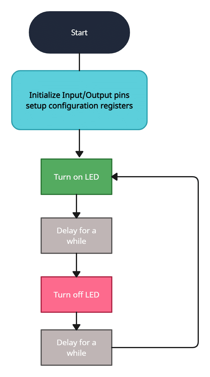
This is the algorithm of the program only. This algorithm says how the program will be executed. Most people do only this and think that it’s all they need and then fall into trouble completing the project. The next part is the architecture which explains how you will make this project look.
Architecture:
This one is similar to the block diagram of the project but it’s little practical to follow. This explains how you will connect your components or blocks of the complete project.
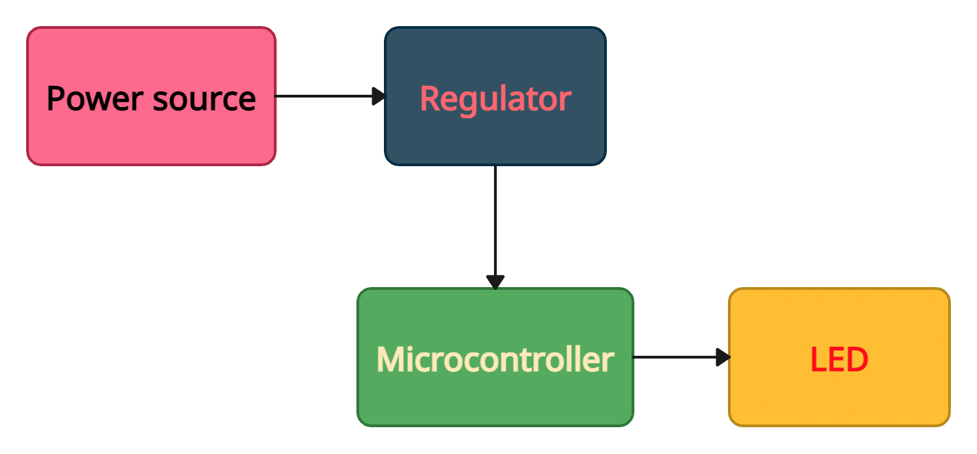
For our first project, it became very simple. However, when a project is made for practical use, this may become very complex. But the fundamental way to follow is to create a block diagram first. This clarifies many things in the project. How you will organize the different inputs, outputs, loads, blocks, sensors, and so on.
Now, our project plan is ready. But still, we need to plan one more thing. How we’ll test the project first. You may do only one simulation or the first simulation and then making in real life. In this project, we’ll do the simulation first. So it is also a part of the project plan.
Step#2: Coding:
Based on the algorithm, we need to code. So let’s do it step by step. First, let’s see the full code, and then I’ll explain part by part. And focus carefully, if you can learn the basic fundamental things, it will be easier to work later on with any microcontrollers.
/*
 Project name: Test Project for learning
 Programmer: Mithun K. Das
 Email: [email protected]
 Date:28-04-2023
*/


void main() {

 TRISB = 0x00;//set all output
 TRISA = 0xFF;//set all input
 TRISC = 0x00;//set all output

 ADCON1 = 0x07;//keep adc off
 ADCON0 = 0x00;//turn off ADC

 PORTB = 0x00;//clear port B
 PORTC = 0x00;//clear port C

 while(1)
 {
    RB0_bit = 1;
    Delay_ms(1000);
    RB0_bit = 0;
    Delay_ms(1000);

 }//end of while(1)
}//end of void main()
This is a very very simple code to blink a LED. now let me explain what is for what.
Code Explanation:
In the first section of main(), you see that I’m using the following lines to set pins either as inputs or outputs.
 TRISB = 0x00;//set all output
 TRISA = 0xFF;//set all input
 TRISC = 0x00;//set all output
Here, TRIS is a Data Direction Register (DDR in short) of this microcontroller, that sets each pin input/output configuration. If you open the datasheet, go to I/O ports page.
For example,
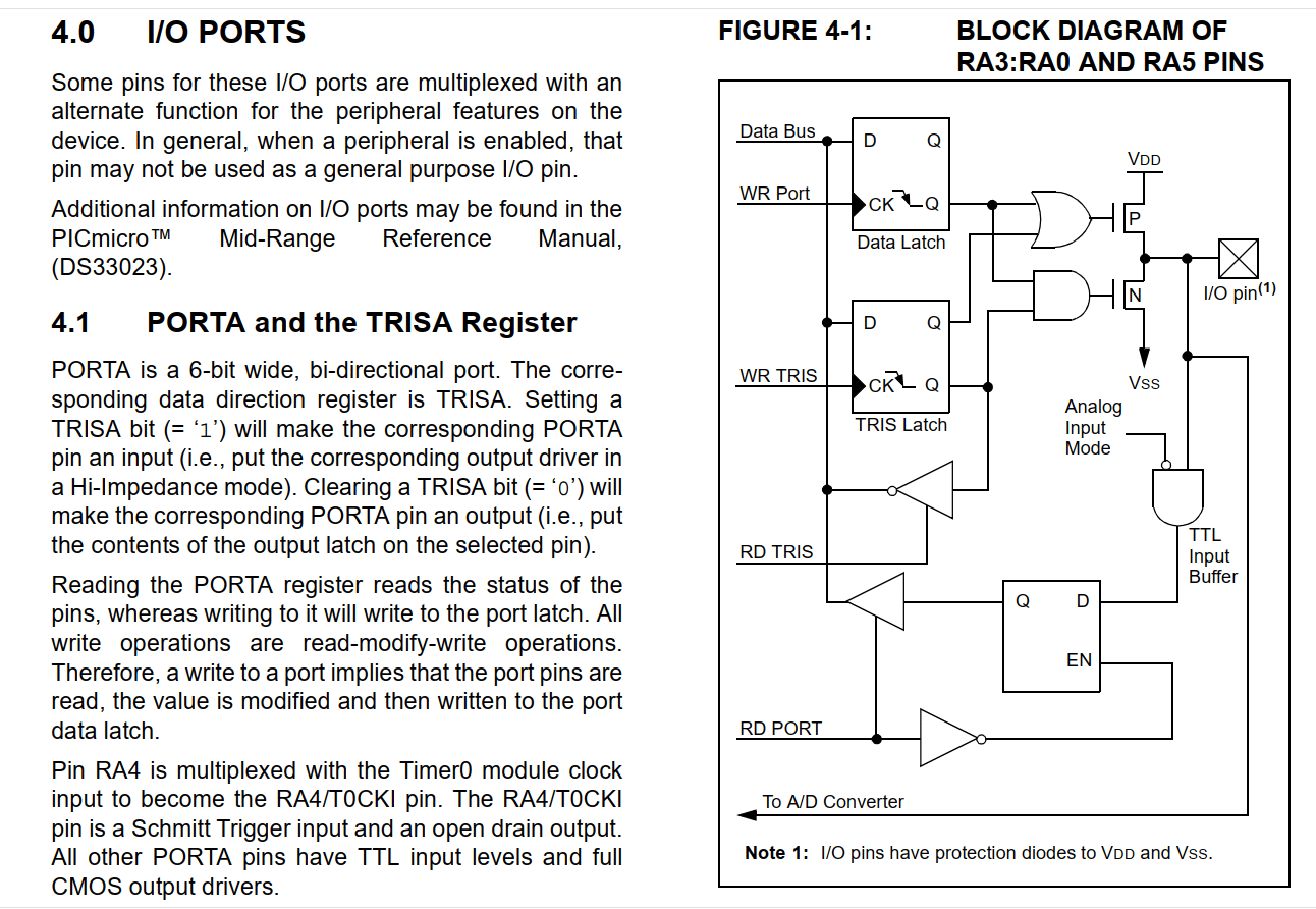
As you can see, TRIS is a register and to properly select with ports, TRISA is the register for port A, Similarly, TRISB is for port B, TRISC is for port C, and so on.
Now, each of these registers is of 8 bits and each of the bits is associated with each pin of that port. So any bit can be set as 0 or 1, where 0 sets that individual pin as output and 1 set as input.
Example:
If you set TRISA0_bit = 1; this will set pin A0 as input. Similarly, if you set TRISA1_bit = 0; this will set pin A1 as output. You can also declare the whole port in one line too.
TRISA = 0b00000010; // here 0b indicating this number is a binary number.
or you can write the same command as this:
TRISA = 0x02; // this is also same as 0b00000010;
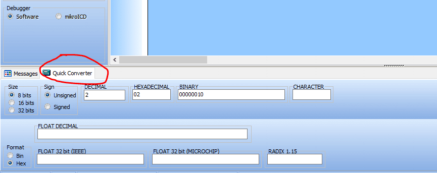
Note: If you still can not convert the numbers, Mikroc Pro for PIC compiler can help you with this. Check the bottom section, you will find a number converter.
I think it is now clear to you how to set a pin or a whole port as input or output with the help of DDR.
now, in the next lines, you can see I wrote:
ADCON1 = 0x07;//keep adc off
ADCON0 = 0x00;//turn off ADC
Here ADCON is the register for ADC. If you do not know what is ADC please read this in the new tab.
Go to the ADC section of the datasheet.
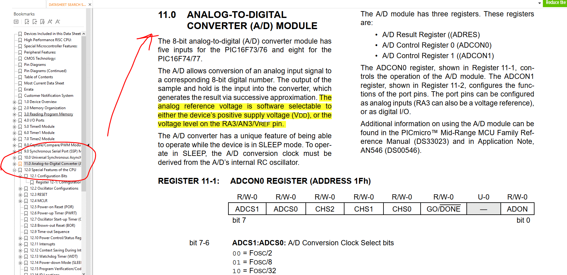
As this is a very basic project, so I do not want to make it complex for you. We’ll discuss ADC later in different upcoming chapters. But for now, we need to disable ADCs. So ADCON1=0x07;//this command will disable the total ADC module and ADCON0=0x00;//this will keep the ADC stopped.
In the following lines,
PORTB = 0x00;//clear port B
PORTC = 0x00;//clear port C
I just cleared the ports which were outputs. Note here that we do not need to clear if the pin/port is set as input.
Infinity loop:
Now in the while(1){... codes } loop, which is actually an infinity loop we can do whatever we need to do repeatedly. That means the microcontroller will do the tasks you write inside this loop forever.
We can set the full port directly by calling PORTB or individual pins by calling RB0_bit where it is calling the B0 pin of port B individually.
RB0_bit = 1; //this is setting B0 pin high
Delay_ms(1000); // is creating a delay of 1000ms or 1sec.
RB0_bit = 0; //this is setting B0 pin low
Delay_ms(1000); // is creating a delay of 1000ms or 1sec.
and these are written inside the while(1) loop. So, the microcontroller will set the B0 pin as high, wait for 1sec, and then it will set the B0 pin as low, and again it will wait for 1sec. And now it will repeat the same process again and again till it has the proper power source.
Step#3: Hex file generation:
We know that the microcontroller does not understand the code we write in different languages. The compiler builds the *.hex file which the microcontroller can read and accept. So, now we need to compile our code and generate the .Hex file to use. To do this, press Ctrl+F9 or click on the build icon on the top.
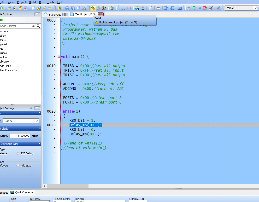
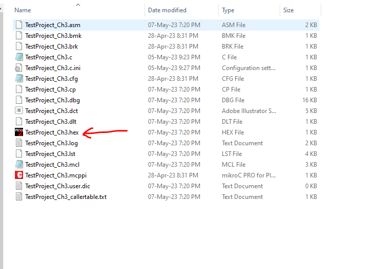
after you click on the build button, it will generate a .hex file which we can use to upload to our microcontroller.
Step#4: Simulation:
For microcontrollers, simulation is an important part. You can check whether your code is working or not. Although it actually depends on how big your code is, and what are the other components and also depends on so many conditions. but for a small coding test like ours, we can simulate our project and see if our code works or not.
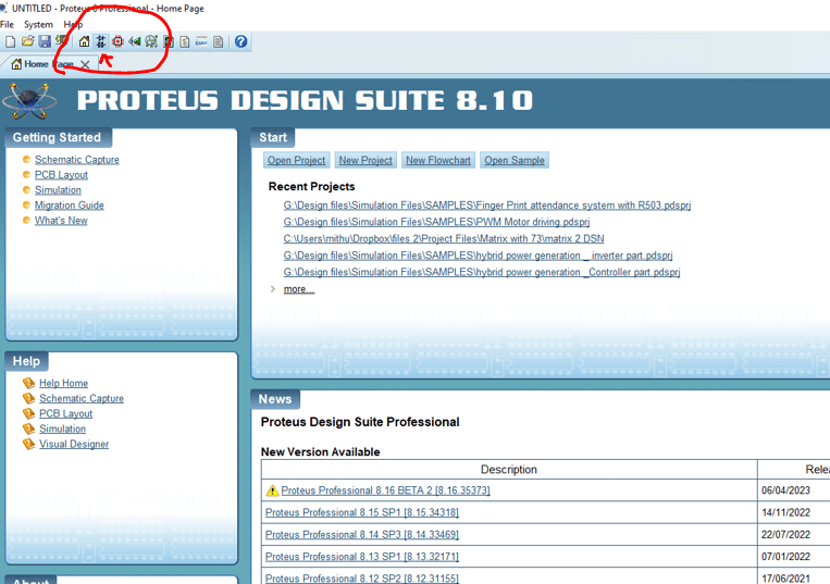
To simulate our project, let’s open Proteus ISIS. Click on Schematic Capture.
Then you will find this page where you can draw your circuit diagram.
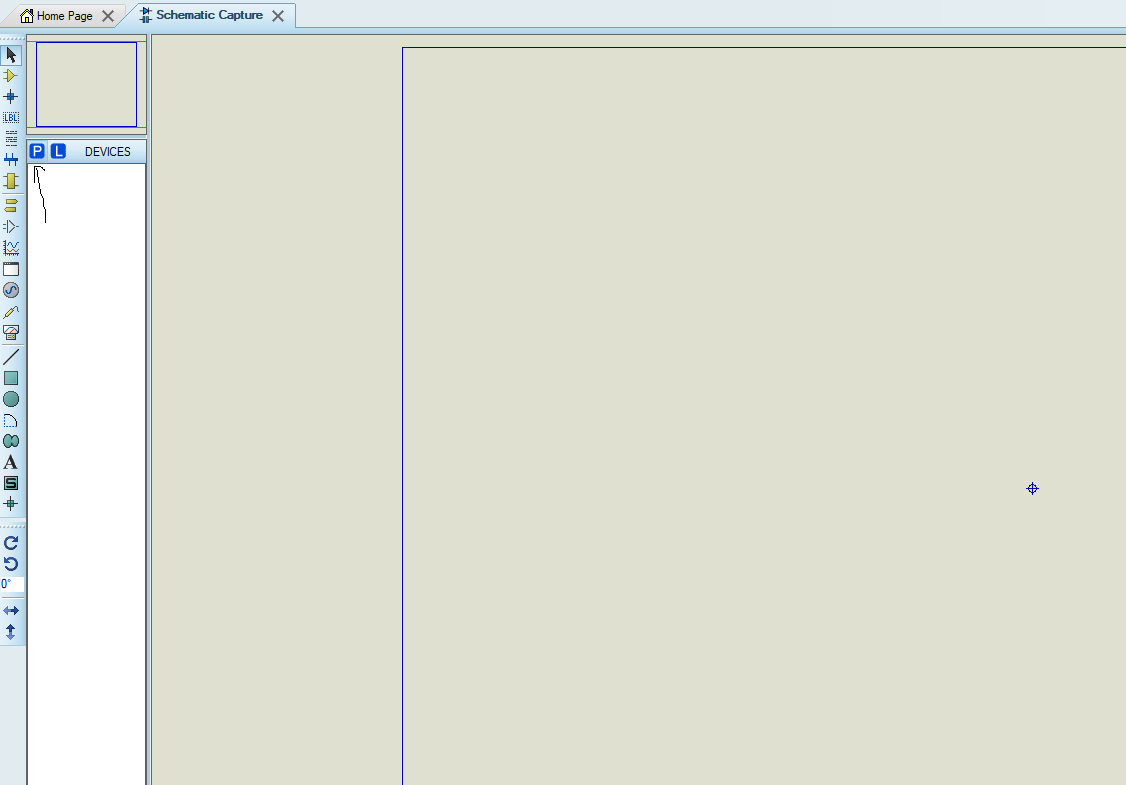
Now, click on P from the DEVICES tab. Find PIC16C73 which is the same as our PIC16F73 in proteus. And then draw the diagram. You can follow mine.
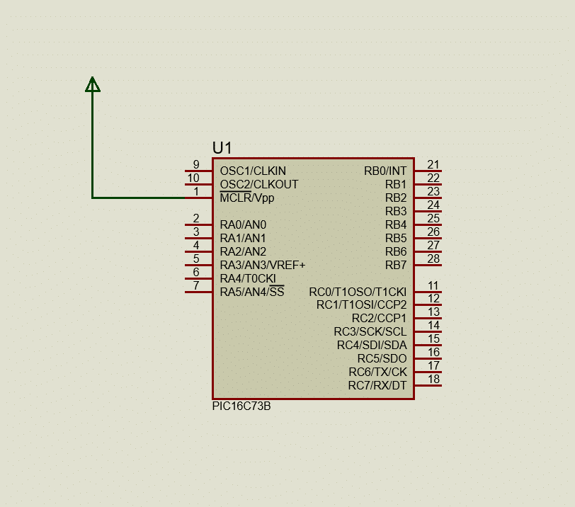
This is the diagram you can draw. Now, you may ask why there is no resistor with the MCLR/Reset pin and also why we need to connect this pin to 5V. Well, those microcontrollers that have the MCLR/Reset option only need to be tied to 5V or logic 1 to keep the MCU running. Some MCUs have input features in this pin where you do not need to tie this pin to logic 1. And touching this pin to 0V or GND will restart the MCU.
And in proteus, we do not need to use any resistor because it will never exceed the current limit while we need to keep a resistor in practical life.
Also, you can ask where is the crystal oscillator. Well, in proteus, we also do not need this to connect in the diagram. We can set it internally from properties while we select our .Hex file. Now, double-click on PIC16C73B.
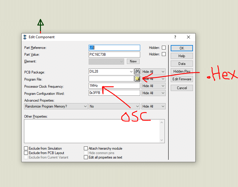
Here, in the program file select your .Hex file and then in the Processor Clock Frequency: set the oscillator value you used in mikroC.
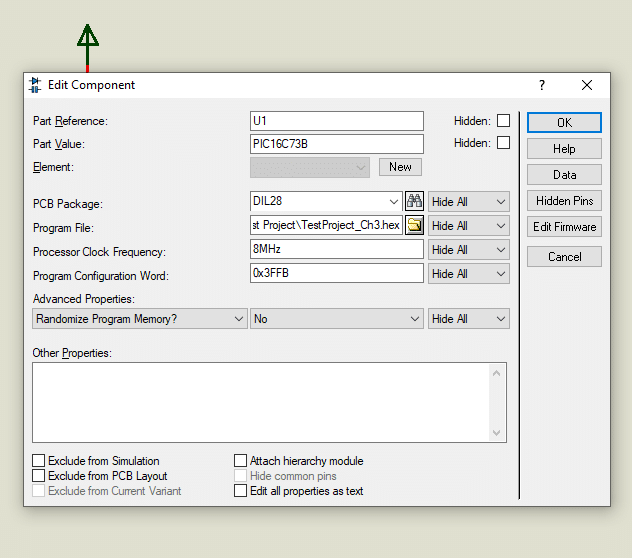
Now click ok and play the simulation from the bottom left corner.
Here you can notice while you are running the simulation, PORTB & PORTC pins are marked blue which means its zero (0V) and only one pin RB0/INT is becoming red (Which means 5V or Logic 1) and then Blue in 1sec interval. That means, it is blinking. Now let’s attach a LED with this pin.
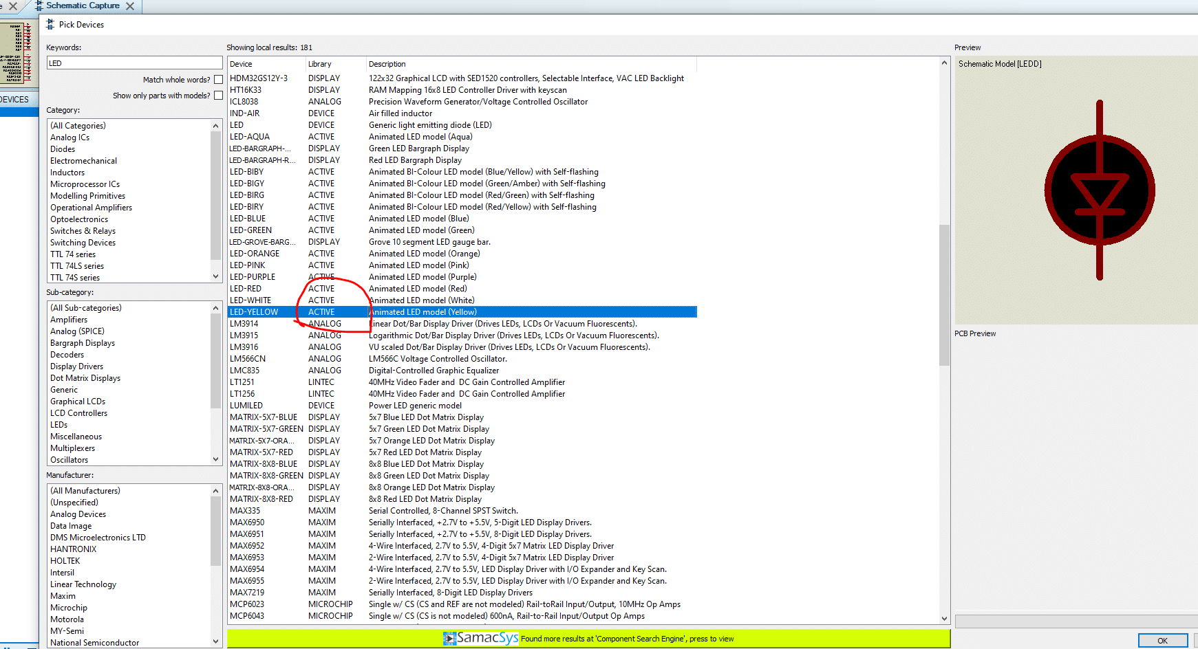
Select Active ones to see the action. Then run the simulation again.

It’s amazing right? Yes, Now you have learned how you can create a small project and follow the process to find it working.
Conclusion:
I hope this basic article will help you learn about microcontrollers. Step by step we will learn many things in the future. So stay with us. Thanks, see you soon.
Read more on:
- Learning PIC Microcontrollers Programming in C: Chapter 3
- Learning PIC Microcontrollers Programming in C: Chapter 2
- Learning PIC Microcontrollers Programming in C: Chapter 1
- Learning PIC Microcontrollers Programming in C: Chapter 5
Liked this article? Subscribe to our newsletter:
or,
Visit LabProjectsBD.com for more inspiring projects and tutorials.
Thank you!


1 Comment
Asimiyu · 11/05/2023 at 2:31 am
Thank you sir. I personally appreciate your details explanation. God bless you. We are flowing with you…