In this chapter, we’ll continue from Chapter 4 which was a practical small project about Learning PIC microcontroller programming in C. So, this chapter also will be a very important part for you to improve your code learning PIC MCU. So follow me with concentration.
⚠️Disclaimer:
Working with electricity involves serious risk. Ensure you have the necessary skills and take proper safety precautions before attempting any electrical projects. Proceed at your own risk — the author assumes no responsibility for any damage, injury, or issues resulting from the use or misuse of the information provided.
All content on this website is original and protected by copyright. Please do not copy or reproduce content without permission. While most of the resources shared here are open-source and freely accessible for your learning and benefit, your respect for our intellectual effort is appreciated.
If you find our tutorials helpful, consider supporting us by purchasing related materials or sharing our work — it helps keep the content flowing.
Need help or have questions? Leave a comment below — the author is always happy to assist!
Table of Contents
Previous chapter:
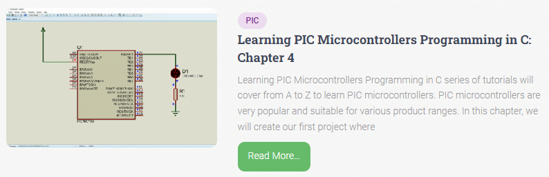
In Chapter 4, we learned to create a small project by just blinking a pin with a delay loop. Now, we need to improve our skills in this. Let’s see how you can improve your coding skill and what alternative things you can do.
Previous code:
/*
 Project name: Test Project for learning PIC MCU
 Programmer: Mithun K. Das
 Email: [email protected]
 Date:28-04-2023
*/

void main() {

 TRISB = 0x00;//set all output
 TRISA = 0xFF;//set all input
 TRISC = 0x00;//set all output

 ADCON1 = 0x07;//keep adc off
 ADCON0 = 0x00;//turn off ADC

 PORTB = 0x00;//clear port B
 PORTC = 0x00;//clear port C

 while(1)
 {
    RB0_bit = 1;
    Delay_ms(1000);
    RB0_bit = 0;
    Delay_ms(1000);

 }//end of while(1)
}//end of void main()
Now practice the following ways which do the same task.
Using Toggoling:
Instead of using 2 delay loops and calling the pin action every time, you can simply toggle the pin with one delay loop. See this:
while(1)
{
RB0_bit = ~RB0_bit;
Delay_ms(1000);
}//end of while(1)
It does the same task.
Benefits:
This reduces code lines but the action is the same.
Using counters:
int Counter=0;
void main() {

 TRISB = 0x00;//set all output
 TRISA = 0xFF;//set all input
 TRISC = 0x00;//set all output

 ADCON1 = 0x07;//keep adc off
 ADCON0 = 0x00;//turn off ADC

 PORTB = 0x00;//clear port B
 PORTC = 0x00;//clear port C

 while(1)
 {

    Counter++;
    if(Counter>100)
    {
      RB0_bit=~RB0_bit;
      Counter=0;
    }
    Delay_ms(10);

 }//end of while(1)
}//end of void main()
This also does the same blinking.
Benefits:
When you need to do other tasks and you can not make a big delay, then you can use this method. Until the counter is reached 100, the pin will not change its state. And you are using a small delay outside. So you have plenty of time to perform other tasks.
Using Timer Interrupt:
When you need precision timing and also, you have lots of tasks to do where the MCU will be inside a delay loop but you need to blink the LED, you can use timer interrupts to do the same task. Note that, I’ll discuss this Timer Interrupt in another chapter.
/*
 Project name: Test Project for learning PIC MCU
 Programmer: Mithun K. Das
 Email: [email protected]
 Date:28-04-2023
*/

void InitTimer1() //10mS timer counter
{
    T1CON	 = 0x01;
    TMR1IF_bit	 = 0;
    TMR1H	 = 0xB1;
    TMR1L	 = 0xE0;
    TMR1IE_bit	 = 1;
    INTCON	 = 0xC0;
}
int Counter=0;
void Interrupt() iv 0x0004 ics ICS_AUTO
{
     if (TMR1IF_bit)
     {
        TMR1IF_bit = 0;
        TMR1H	 = 0xB1;  //10mS timer interrupt
        TMR1L	 = 0xE0;
        //Enter your code here
        Counter++;
        if(Counter>100)
        {
          RB0_bit=~RB0_bit;
          Counter=0;
        }
     }

}
void main() {

 TRISB = 0x00;//set all output
 TRISA = 0xFF;//set all input
 TRISC = 0x00;//set all output

 ADCON1 = 0x07;//keep adc off
 ADCON0 = 0x00;//turn off ADC

 PORTB = 0x00;//clear port B
 PORTC = 0x00;//clear port C

 InitTimer1();

 while(1)
 {

    //do other tasks in while loop
    Delay_ms(5000);

 }//end of while(1)
}//end of void main()
Benefits:
You got it already. Yes, when you need precision timing and you have other tasks in a while loop where MCU can be inside the delay loop but you need to blink the LED, you can use this way.
To understand the timer interrupt, you can see this code where I’m blinking two LEDs, one as before and another one inside the while(1) loop which is blinking 5 seconds interval.
/*
 Project name: Test Project for learning PIC MCU
 Programmer: Mithun K. Das
 Email: [email protected]
 Date:28-04-2023
*/

void InitTimer1()
{
    T1CON	 = 0x01;
    TMR1IF_bit	 = 0;
    TMR1H	 = 0xB1;
    TMR1L	 = 0xE0;
    TMR1IE_bit	 = 1;
    INTCON	 = 0xC0;
}
int Counter=0;
void Interrupt() iv 0x0004 ics ICS_AUTO
{
     if (TMR1IF_bit)
     {
        TMR1IF_bit = 0;
        TMR1H	 = 0xB1;
        TMR1L	 = 0xE0;
        //Enter your code here
        Counter++;
        if(Counter>100)
        {
          RB0_bit=~RB0_bit;
          Counter=0;
        }
     }

}
void main() {

 TRISB = 0x00;//set all output
 TRISA = 0xFF;//set all input
 TRISC = 0x00;//set all output

 ADCON1 = 0x07;//keep adc off
 ADCON0 = 0x00;//turn off ADC

 PORTB = 0x00;//clear port B
 PORTC = 0x00;//clear port C

 InitTimer1();

 while(1)
 {

    //do other tasks in while loop
    RB1_bit=~RB1_bit;
    Delay_ms(5000);

 }//end of while(1)
}//end of void main()
See, they are doing their own job. And all these blinking actually present two different tasks. One task is running in a while loop and another task is running background. I’ll explain about the timer interrupt later on when it’s time to discuss this in an easy way. And if you can not wait, you can read this to learn about timer Interrupts. But till this far, practice all of these. See you soon.
Read more on:
- Learning PIC Microcontrollers Programming in C: Chapter 1
- Learning PIC Microcontrollers Programming in C: Chapter 2
- Learning PIC Microcontrollers Programming in C: Chapter 3
- Learning PIC Microcontrollers Programming in C: Chapter 4
- Learning PIC Microcontrollers Programming in C: Chapter 6
Liked this article? Subscribe to our newsletter:
or,
Visit LabProjectsBD.com for more inspiring projects and tutorials.
Thank you!


10 Comments
iffi · 19/05/2023 at 11:34 pm
Hi, Sir i like your teaching and succeed in blinking program.
My Question is ” if i want to control the Brightness of an led with push buttons , i need the timer and intruppts for that ” ??
Thnx for lessons.
MKDas · 20/05/2023 at 12:46 pm
Soon there will be similar articles in future.
iffi · 22/05/2023 at 6:34 am
void InitTimer1()
{
T1CON = 0x01;
TMR1IF_bit = 0;
TMR1H = 0xB1;
TMR1L = 0xE0;
TMR1IE_bit = 1;
INTCON = 0xC0;
}
int Counter=0;
You didn’t discuss about these ??
MKDas · 22/05/2023 at 11:52 am
Read the article top to bottom please. This is s series of learning phase. When its time to discuss about timer, I’ll do that.
Md Ariful Islam · 08/06/2023 at 11:14 am
sir, come one such post capable of calculating duty cycle from dead time pwm with adc
MKDas · 08/06/2023 at 11:22 am
coming soon
MD ARIF · 18/06/2023 at 2:20 pm
short toggle=0;
void InitTimer0(){
OPTION_REG = 0x87;
TMR0 = 61;
INTCON = 0xA0;
}
void Interrupt(){
if (TMR0IF_bit){
TMR0IF_bit = 0;
TMR0 = 61;
//Enter your code here
{
toggle = ~ toggle;
}
if(toggle)
{
RB0_bit = 0;
RB1_bit = 1;
}
else
{
RB0_bit = 1;
RB1_bit = 0;
}
}
}
void main()
{
TRISB = 0x00;//all output
PORTB = 0x00;//all clear
InitTimer0();
while(1)
{
}
}
// sir, Tried to generate pwm through this timer for push pull work,,, here I want to use adc to make duty cycle less basic,. I will benefit a lot if you help me.
MKDas · 18/06/2023 at 6:50 pm
Your interrupt function is not in right format. Create interrupt function from compiler option. IVS auto and vector etc.
Md Arif · 24/06/2023 at 4:43 pm
void Timer0_interrupt() iv 0x0004 ics ICS_AUTO
sir,
How to use ADC here?
MKDas · 02/07/2023 at 7:29 pm
ADCs are not supported inside interrupt in lower level MCUs.