Maximizing power output from solar panels is essential for efficient energy utilization, and this is where an MPPT (Maximum Power Point Tracking) Solar Charge Controller comes into play. In this article, we’ll explore how an MPPT Solar Charge Controller works and guide you through building one yourself. Whether you want to power your home or integrate it into a product with minor modifications, this project is versatile and practical. Let’s dive in!
⚠️Disclaimer:
Working with electricity involves serious risk. Ensure you have the necessary skills and take proper safety precautions before attempting any electrical projects. Proceed at your own risk — the author assumes no responsibility for any damage, injury, or issues resulting from the use or misuse of the information provided.
All content on this website is original and protected by copyright. Please do not copy or reproduce content without permission. While most of the resources shared here are open-source and freely accessible for your learning and benefit, your respect for our intellectual effort is appreciated.
If you find our tutorials helpful, consider supporting us by purchasing related materials or sharing our work — it helps keep the content flowing.
Need help or have questions? Leave a comment below — the author is always happy to assist!
Table of Contents
What is a Solar Power System?

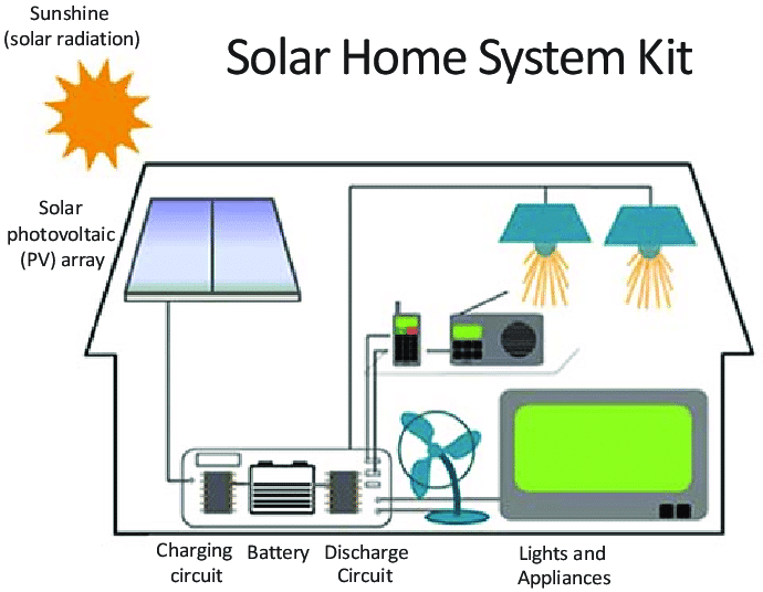
Before we dive deeper, let’s first understand what a solar home system (or solar power system) actually is. Solar energy comes from the Sun, and sunlight can be converted into electricity using a solar panel, which is made of semiconductor materials (typically P-N junctions).
The electricity generated is direct current (DC), which can either be stored in a battery or used directly to power appliances such as lights and fans. However, since most household appliances run on alternating current (AC), an inverter is often required to convert the DC power into AC.
- A complete solar home system typically consists of:
- A charge controller (to regulate charging and protect the battery)
- A solar panel (for power generation)
- A battery (for energy storage)
- An inverter (to convert DC into AC, if needed)
What is a Storage(Battery) in the solar home system?
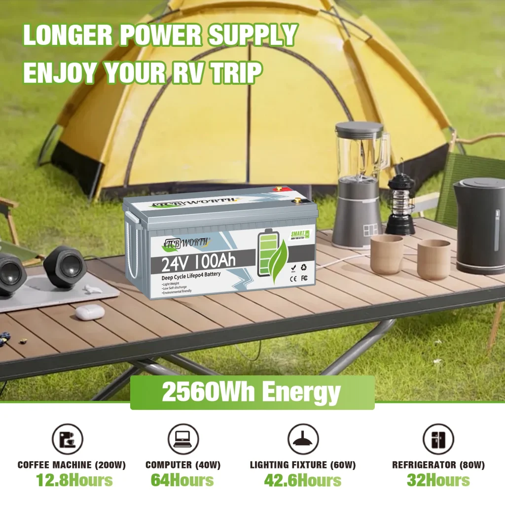
Solar home systems and solar power systems rely on batteries as energy storage devices. While traditional lead-acid batteries are the most commonly used due to their affordability, AGM (Absorbent Glass Mat) and lithium-ion batteries are also popular alternatives, especially in more advanced systems. Among these, lithium-ion batteries stand out as the most efficient and durable option, though their higher cost often makes them less practical for smaller systems, where lead-acid batteries remain the preferred choice.
Regardless of the battery type, each has specific charging and discharging characteristics that must be adhered to for optimal performance and longevity. Every battery has a maximum charging voltage, which should not be exceeded, and a minimum discharge voltage, below which the battery should not be depleted to avoid damage or significantly reduced lifespan. Proper management of these thresholds is critical to ensure the reliability and durability of the solar power system
If we consider a lead-acid battery of 12V, a higher cut-off point will be 14.3V-14.6V (varies by different manufacturers). And a lower discharging point will be 11.5V-11.6V. That means, this battery should not be charged over 14.6V and should not be discharged below 11.5V.
That is why a charge controller is required between the Solar panel and the battery.
More articles:
- Step-by-Step Guide to Building an MPPT Controller with Arduino and a Synchronous Buck Converter
- Solar Charge Controller circuit & working principle of ON/OFF charge controller
- A smart Battery charger circuit design guide
- Get long life of your Lead-Acid battery by selecting the right charging method
- How I Built a Smart Home Relay Module for Under $5 (DIY Guide 2025)
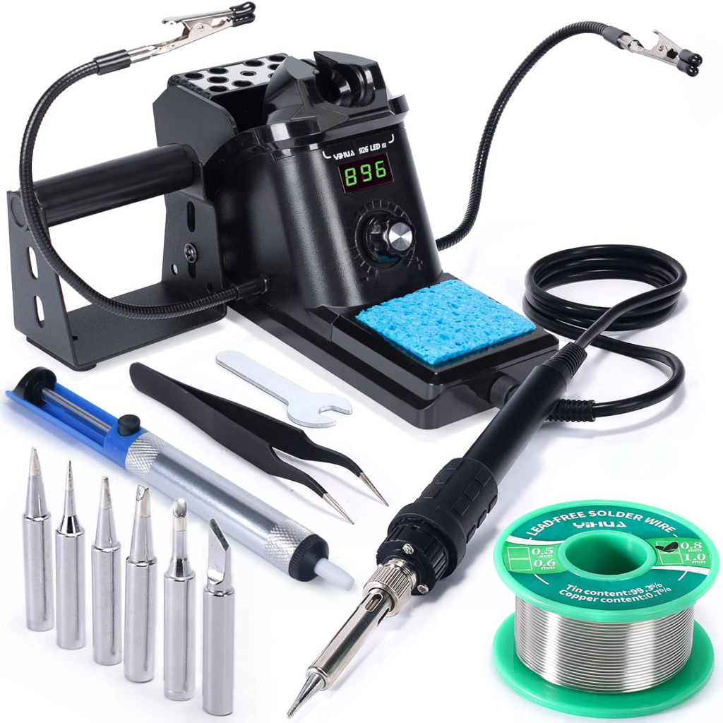
Check out these awesome soldering iron sets:
What is a solar panel?
The term solar panel is used colloquially for a photo-voltaic (PV) module.
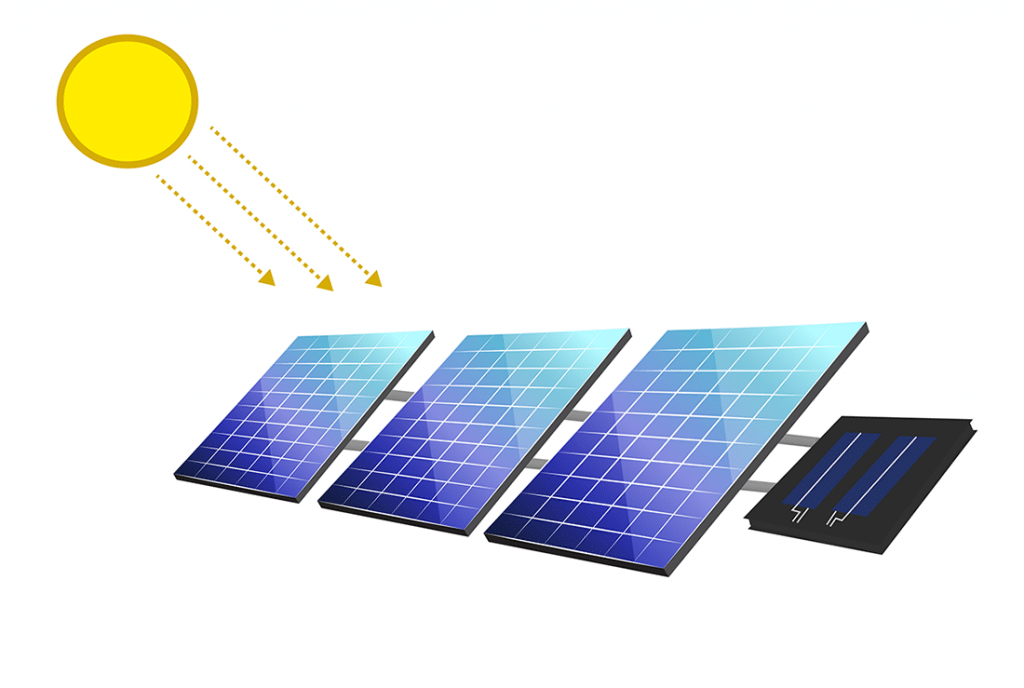
A PV module is an assembly of photovoltaic (solar) cells mounted in a protective framework for installation. These cells capture sunlight and convert it into direct current (DC) electricity.
When multiple PV modules are grouped together, they form a PV panel, and a collection of panels is known as a solar array. Solar arrays are the core of a photovoltaic system, providing clean solar electricity to power electrical equipment. (Learn more about solar panels on Wikipedia.)
Now, let’s move on to the next important component of a solar home system: the solar charge controller. This device regulates the power coming from the solar panels to the battery, ensuring safe and efficient charging.
There are three main types of solar charge controllers available in the market. Let’s take a closer look at them.
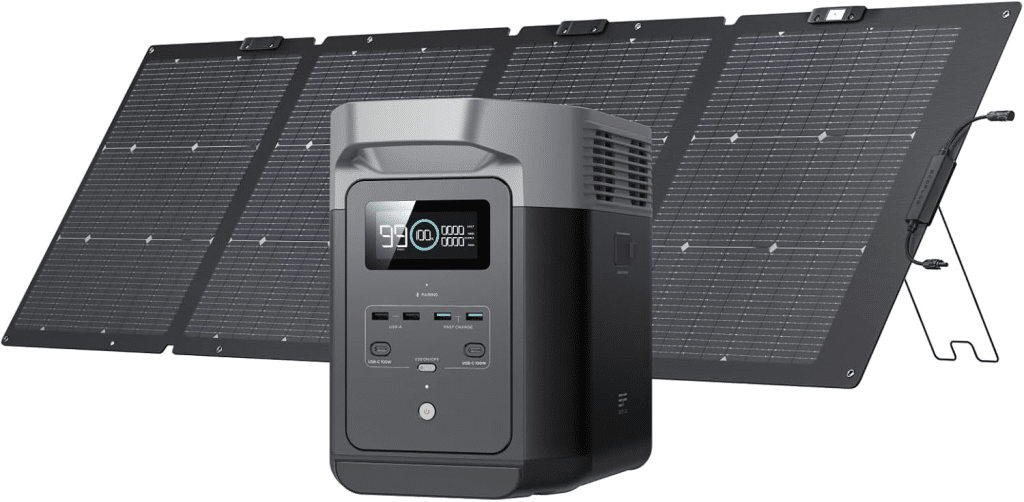
You can check these solar panels for your solar home system:
What is a solar charge controller?
The solar charge controller is a device that controls the charging, and some of them also control the discharging of the battery. Normally, it consists of a switch between a solar panel and a battery. Controlling this switch, charging is regulated.
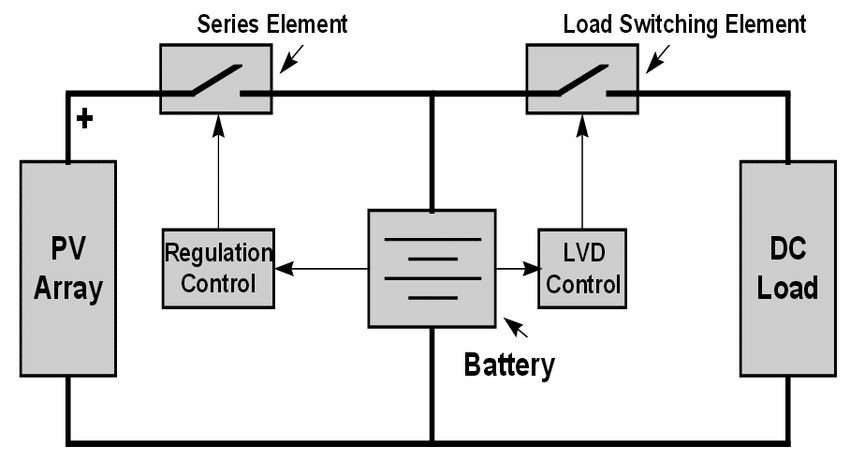
Depending on the charging mechanism, charge controllers can be differentiated into 3 types.
- On/Off type charge controller
- PWM-type charge controller
- MPPT-type charge controller
What is an On/Off type charge controller?
An on/off type charge controller is the most basic one, which has only an on/off switch, like a MOSFET/Transistor/even relay, and a controller (Analog circuit / micro-controller).
pros:
- Very easy circuit diagram
- Simple operation
- Low cost
cons:
- Very low efficiency
- Less charging
Due to their very low efficiency, on/off type charge controllers are used in only very limited systems. They are employed primarily in situations where efficiency is not a major concern. If a 12V solar panel has an open-circuit voltage of 22V, and the 12V system has a 12V battery, an on/off type charge controller can connect the photovoltaic (PV) panel to the battery almost directly. This means that the 22V – 12V = 10V difference is not utilized effectively. Consequently, if the panel provides 5A of current, the power loss will be 10V x 5A = 50 watts. Even considering the panel operating at its peak power point (approximately 16.5V), there is still a loss of at least (16.5V – 12V) x 5A = 22.5 watts.
For this type of loss, an On/off type solar charge controller is used in limited systems.
What is a PWM-type solar charge controller?
PWM (Pulse Width Modulation) Charge Controller
A PWM charge controller is an advanced version of the basic on/off solar charge controller. Instead of simply switching the charging process on or off, it uses a pulse-width modulation (PWM) signal to regulate the charging current more efficiently.
Compared to the simple on/off type, a PWM controller provides smoother and more controlled charging of the battery. This helps to reduce stress on the battery, minimize heating, and extend overall battery life.
However, one limitation of PWM controllers is that they cannot always extract the maximum available power from the solar panels. For this reason, they are less efficient than modern MPPT (Maximum Power Point Tracking) controllers, especially when there is a significant difference between the solar panel voltage and the battery voltage.
pros:
- Smoother charging control
- Longer battery life
- Low price
cons:
- Less efficient than MPPT
- Power loss
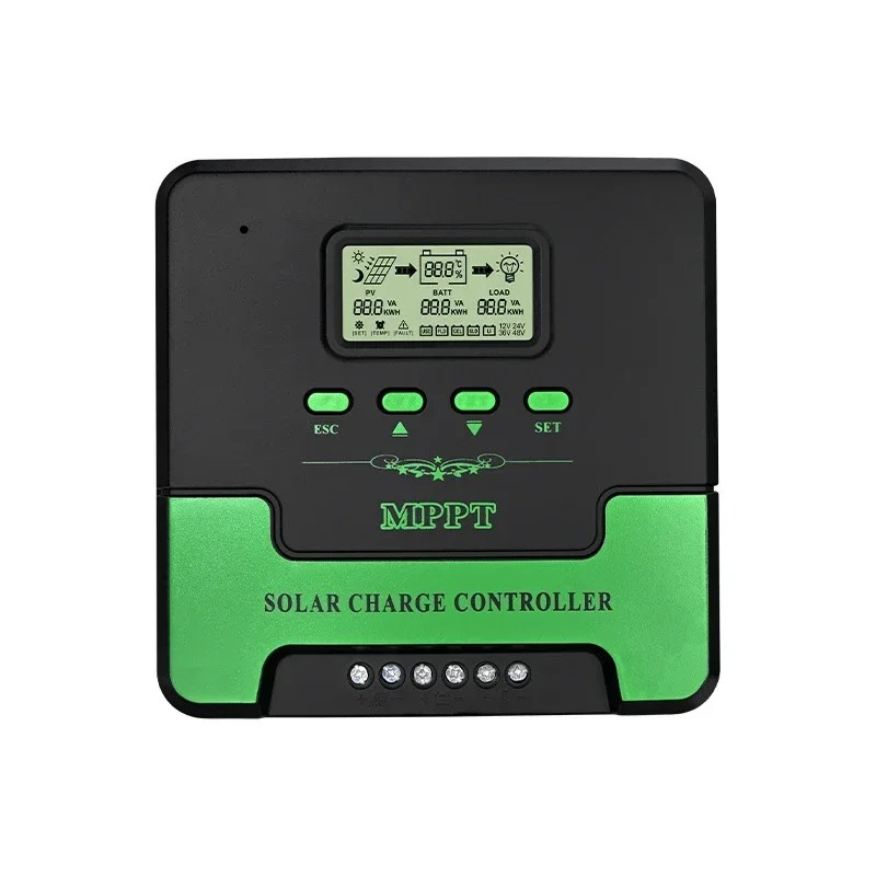
What is an MPPT solar charge controller?
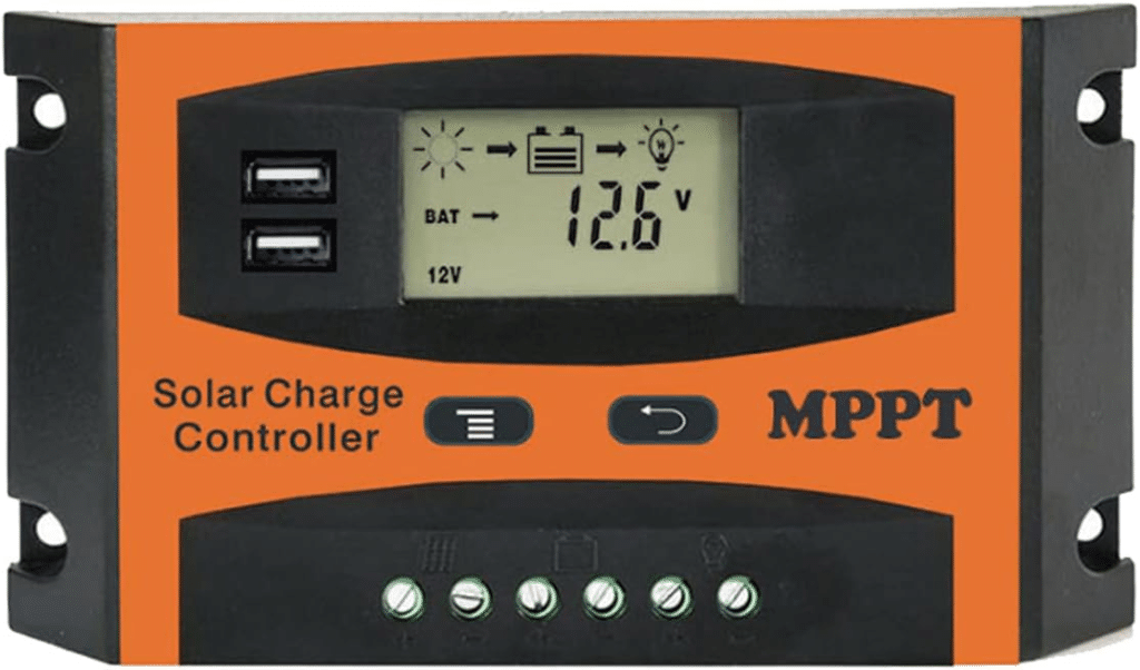
The MPPT solar charge controller is a type of DC/DC converter that delivers the maximum power generated by the solar panel to the battery, allowing it to store the charge. It is the most complex one among solar charge controllers. The MPPT solar charge controller mostly has only a charging part. That means it only controls the solar panels for battery charging. For load control, another device may be required depending on the power system.
pros:
- Highly efficient charging
- Best energy management
- Proper utilization of battery charging
cons
- High cost
- Complex circuitry.
We have known types of charge controllers; now, let’s see more about MPPT solar charge controllers.
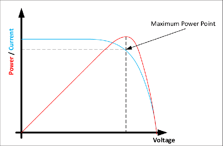
Why do we need an MPPT solar charge controller?
An MPPT solar charge controller is necessary for any solar power system that needs to extract maximum power from the PV module; it forces the PV module to operate at a voltage close to the maximum power point to draw maximum available power. MPPT solar charge controller reduces the complexity of the system, while the output of the system is highly efficient.
Each solar panel (PV) produces its maximum power at about 17V (16.5V in most cases). This point is known as MPP or Maximum PowerPoint. So the MPPT solar charge controller has to maintain PV voltage at this MPP so that the available maximum power can be harvested from that solar panel (PV).
MPPT Charge Controller basic parts:
MPPT solar charge controller has a basic part, a DC/DC converter, a sensing part, and a controller. The controller senses PV voltage and current and sends this data to the controller. The controller calculates the recent power, compares this power with the previous power, and decides what to do next. Changing control pulses, control maintains the DC/DC conversion at the point where the maximum power can be obtained at that time.
Now we have some basic parts in the MPPT solar charge converter:
- A DC/DC converter
- Voltage and Current sensor and
- A controller
- Algorithm for MPPT.
Let’s see one by one next.
Find more:
- DC/DC converter using Transistors
- Buck converter using NE555 and N-Channel MOSFET
- BUCK converter using low-side N-Channel MOSFET
- How to reduce noise from DC motor
- All-in-One Electronic tools and Calculators links
What is a DC/DC converter?
A DC/DC converter is a converter where the output voltage can be lower or higher than the input voltage. Based on the configuration, DC/DC converters can be divided into these types:
- Buck Converter
- Boost Converter
- Buck-Boost converter
- Ćuk Converter
What is a Buck converter?
The buck converter is a step-down converter. Here, the Output voltage is lower than the input voltage. A basic diagram of a buck converter is:

Types of Buck converter?
Based on the switching configuration, buck converters can be divided into two types.
- Synchronous Buck converter
- Asynchronous Buck converter
We will discuss the Synchronous buck converter later.
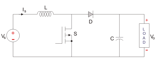
What is a Boost converter?
The boost converter is one kind of step-up converter where the output voltage is higher than the input voltage. A basic diagram of the boost converter is:
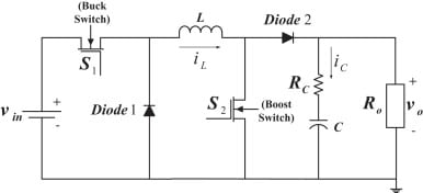
What is a buck-boost converter?
The buck-boost converter is a combined DC/DC converter. Here, the output voltage can be higher or lower than the input voltage. By controlling two PWMs, the output can be controlled. The basic diagram for the buck-boost converter is:
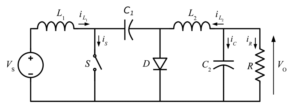
What is Ćuk Converter?
The Ćuk converter is a type of DC/DC converter that has an output voltage magnitude that is either greater than or less than the input voltage magnitude. It is essentially a boost converter followed by a buck converter with a capacitor to couple the energy.
Take a coffee break if you feel bored:
What is a Synchronous Buck Converter?
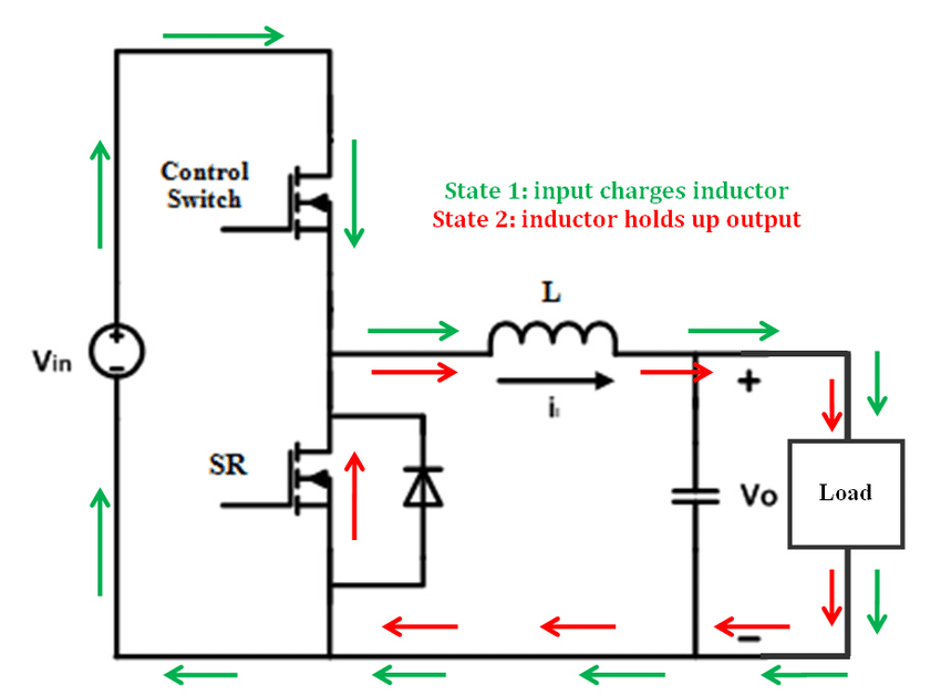
In an asynchronous buck converter, a diode is connected in reverse (freewheeling diode) to provide a path for the inductor current when the main switching device is off. However, this diode introduces a forward voltage drop (typically around 0.7V for a silicon diode), which results in power loss and reduces the overall efficiency of the converter.
To improve efficiency, the diode can be replaced with a MOSFET operating as a synchronous rectifier. Since the MOSFET has a much lower on-resistance (R<sub>DS(on)</sub>), the effective voltage drop across it can be as low as 0.1V (or even less depending on the MOSFET). This significantly reduces conduction losses and increases the overall efficiency of the buck converter.
This approach is commonly known as a synchronous buck converter.
Use:
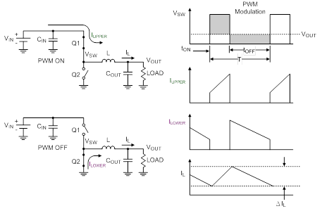
The synchronous buck converter is used to step down a voltage from a higher voltage to a lower voltage. Synchronous buck converters are very popular in the industry today and provide high-efficiency solutions for a wide range of applications. This application note gives the formulas to calculate the power stage of a synchronous buck operating in continuous conduction mode. An asynchronous buck converter produces a regulated voltage that is lower than its input voltage and can deliver a high current while minimizing power loss. As shown in Figure 1, the synchronous buck converter comprises two power MOSFETs, an output inductor, and input and output capacitors.
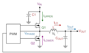
Q1, the high-side MOSFET, is connected directly to the input voltage of the circuit. When Q1 turns on, IUPPER is supplied to the load through Q1. During this time, the current through the inductor increases (charging L) and Q2 is off. When Q1 turns off, Q2 turns on and ILOWER is supplied to the load through Q2. During this time, the inductor current decreases (discharging L). Figure 2 shows the basic waveforms for the synchronous buck converter in continuous conduction mode.
To learn more about Synchronous buck converter design, please read these documents:
Download Application Notes for the buck converter design guide.
Inductor design guide:
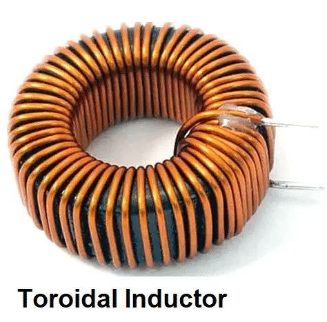
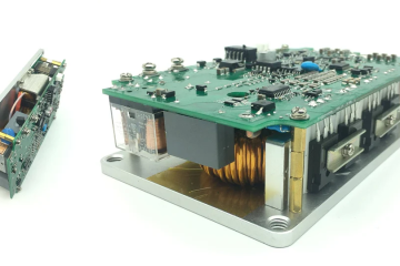
The inductor is one of the most critical components in a DC/DC converter. Selecting and designing the right inductor can be a bit complex, as it directly affects the performance and efficiency of the converter.
In our project, we used a toroidal core inductor. For the design calculations, I used the online tool available at coil32.net, which is very helpful for estimating the required inductance and winding details.
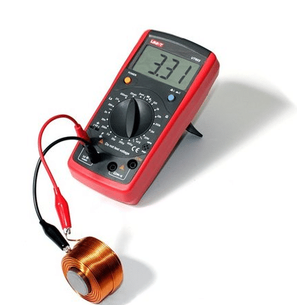
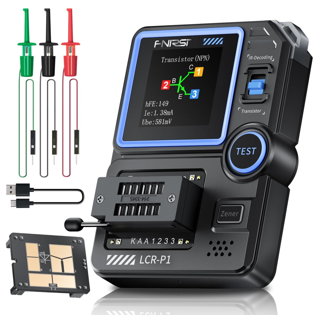
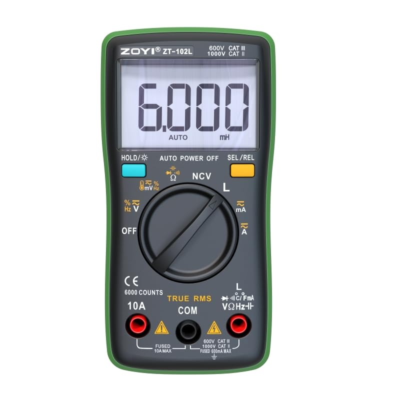
Once the inductor is built, it’s important to verify the inductance before assembling the circuit. For this, I used an RLC meter to measure the inductance and ensure it matched the design requirements.
Read more:
All-in-One Electronic tools and Calculator links
Voltage and current sensing unit:
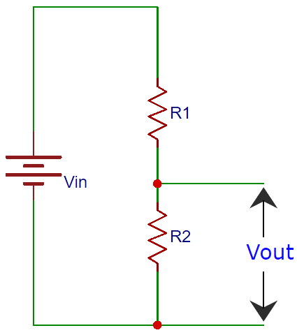
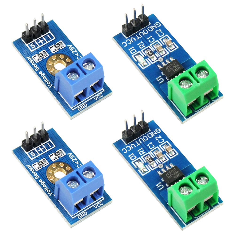
Voltage can be sensed easily using a resistor voltage divider and a capacitor filter, like this circuit:
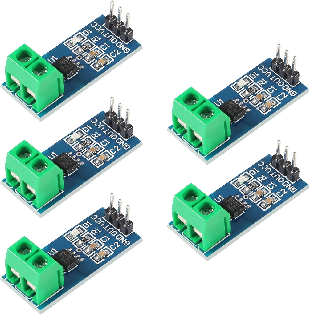
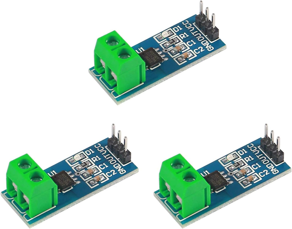
But to sense current, using a Hall-effect sensor is a more efficient way than using a series resistor. Here in this project, we’ll use the ACS712-30 hall-effect-based current sensor.
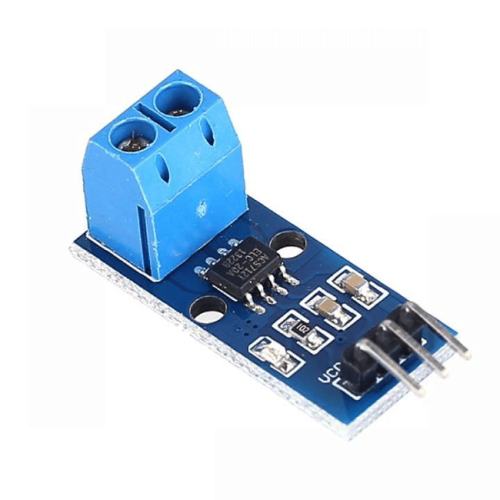
This current sensor provides a linear DC voltage corresponding to the current flow. Neutral point is 2.5V (where the supply voltage is 5V). Positive or negative current flow generates a linear voltage at the output terminal, either higher than 2.5V or lower than 2.5V, respectively.
ACS712-30A gives 66mV/Amp deflection according to the input current flow. We can easily integrate this current sensor into our circuit as the current sensor.
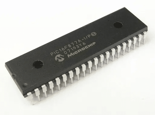
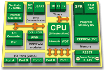
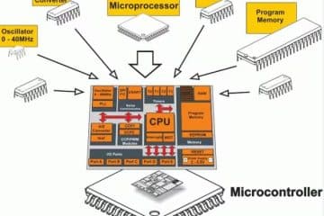
About the controller:
As the controller, we can use a microcontroller. Or we can say that we have to use a microcontroller to control everything. Here in this project, we will use the PIC16F877A microcontroller.
Algorithm:
For Maximum PowerPoint Tracking, an algorithm is very important. Depending on the algorithm, the total design can be changed. For MPPT charge controllers, the most common algorithms are listed below:
- Perturbation and Observation (P&O)
- Incremental Conductance (IncCond)
- Ripple Correlation
- Constant Voltage
- Open-Circuit
- Current sweep
- Temperature Method
- Fractional open-circuit voltage
Discussing individually will be too lengthy. I’m requesting you to study this yourself.
Other parts of MPPT solar charge controller:
Besides the main parts of the MPPT solar charge controller, we also need to focus on other associated parts for our Project.
- Input and output protections
- Gate driver for MOSFETs
- Visualization of information
- Bluetooth data logging
- SMPS mobile charging
- Power supply for circuit parts.
- Load control unit
Input and Output protection:
Input and output should be protected from reverse flow, and a current-limiting resistor must be introduced.
For reverse flow, a Diode can be used. But as efficiency is an issue, we have to eliminate this diode by a MOSFET. The MOSFET also has a body diode. If we use the MOSFET in a reverse way, the body diode will work as a normal diode, and while switching the upper MOSFET of the Synchronous buck converter, if we switch this MOSFET, it will short the diode. That means the voltage drop will be less than 0.1V. Thus, we can reduce loss as well as efficiently use a diode. This configuration in our project will be:
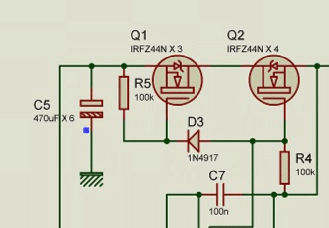
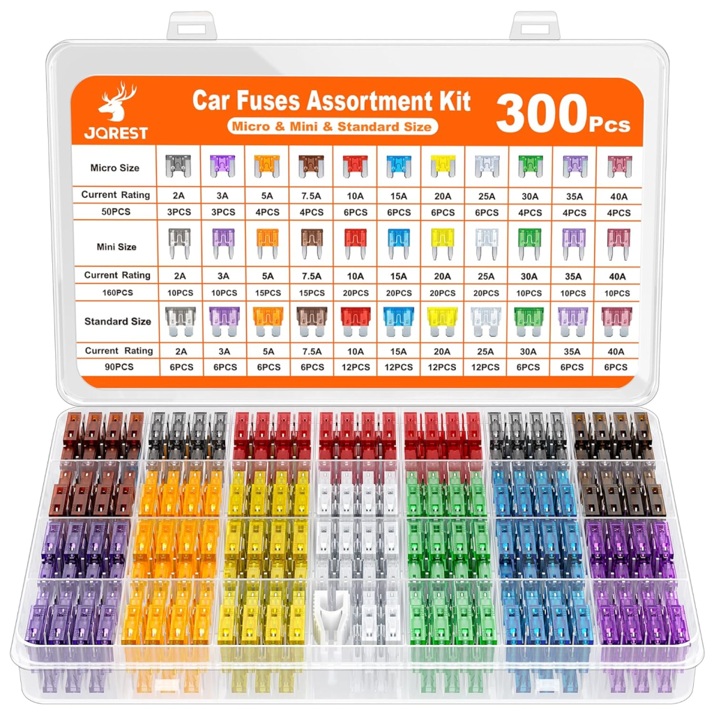
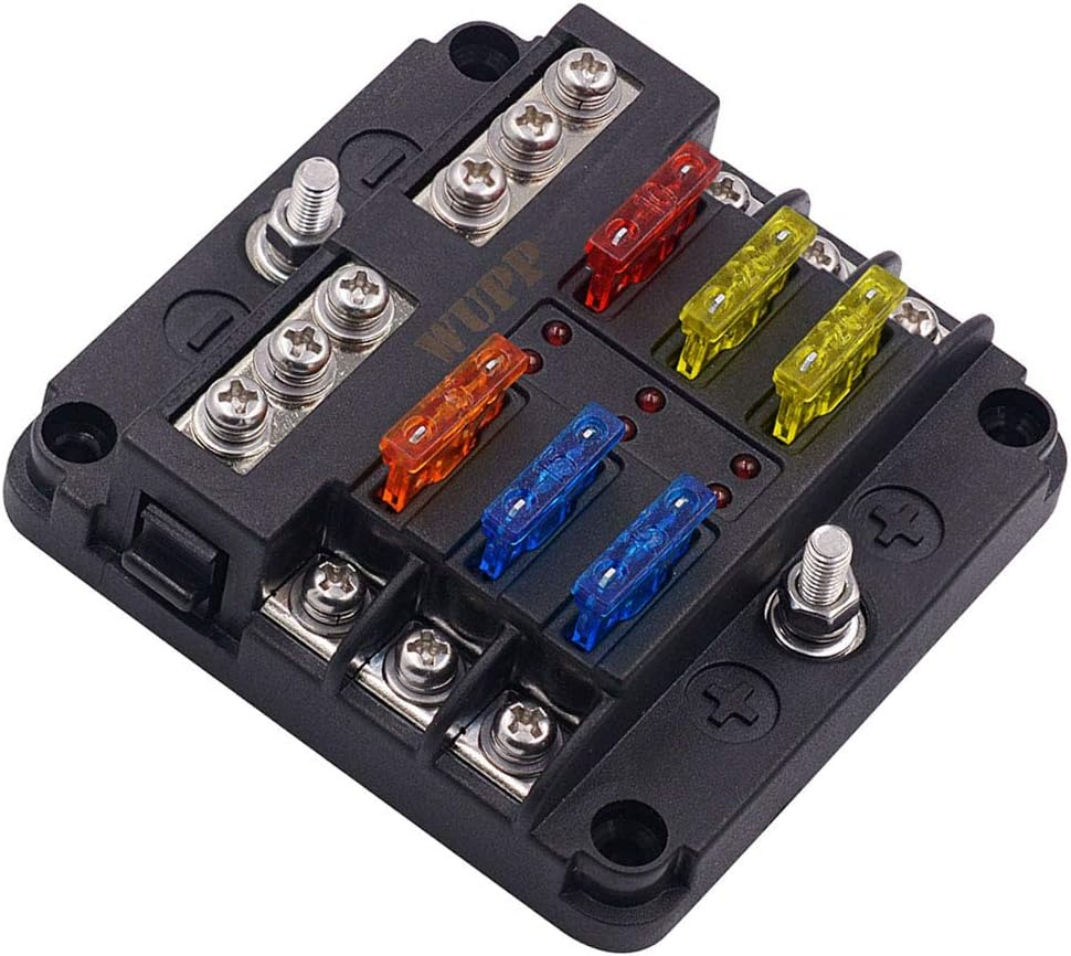
For the current limit, we can use Fuses. Using a DC fuse is a good idea, but if there is no DC fuse nearby, we can use common fuses.
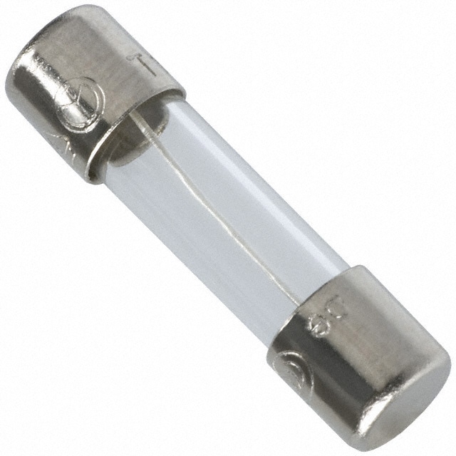
But you can use DC fuses if you want:
Gate Driver circuit:
Most of the micro-controllers work at a 5V supply, and others are 3.3V or even 2.5V range. But the MOSFETs need at least 10V across the Gate and Source for switching. Otherwise, the conductivity will be low, which generates heat, and in the end, the MOSFET blows out. As our microcontroller can not provide more than 5V, we need a gate driving circuit. This circuit can be designed in multiple ways depending on the circuit configuration.
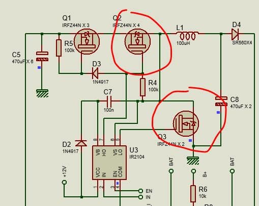
In our circuit:
Here in this project, the DC/DC converter is a Synchronous Buck type. In the synchronous buck converter, we already know that there are two MOSFETs. One is the upper MOSFET, and the other is the lower MOSFET.
Gate signals:
The gate signal of these two MOSFETs is inverted from each other type like this:
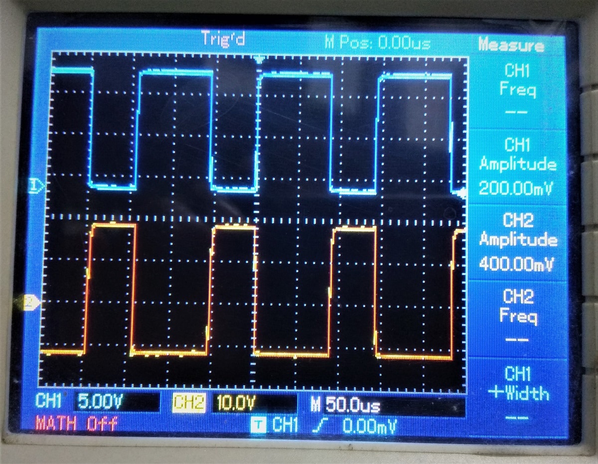
Here, the blue one on the top is the gate driving signal of the upper MOSFET, and the red one on the bottom is the gate driving signal for the lower MOSFET. In this way, the back emf of the inductor can be passed through the lower MOSFET, which was generated by the upper MOSFET switching. This way, the synchronous buck converter works.
Why do we need a gate-driving IC?
As you see, the gate driving mechanism in the Synchronous buck converter is a little bit complex. A dedicated gate-driving IC can do this job efficiently. That is why we need a gate-driving IC.
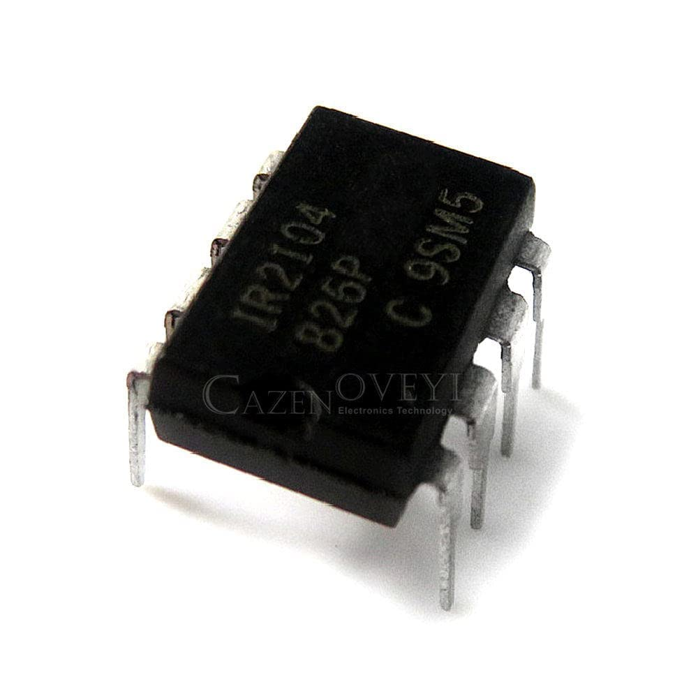
Here, IR2104 is one of the suitable gate-driving ICs for Synchronous buck converters.
Aboutthe IR2104 gate driving IC:
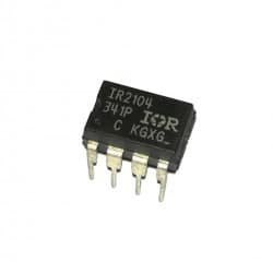
IR2104 is a dedicated gate driving IC for the half-bridge drivers, which is actually a kind of Synchronous buck converter gate driver IC.
Check the datasheet of IR2104 here to understand this gate driver IC.
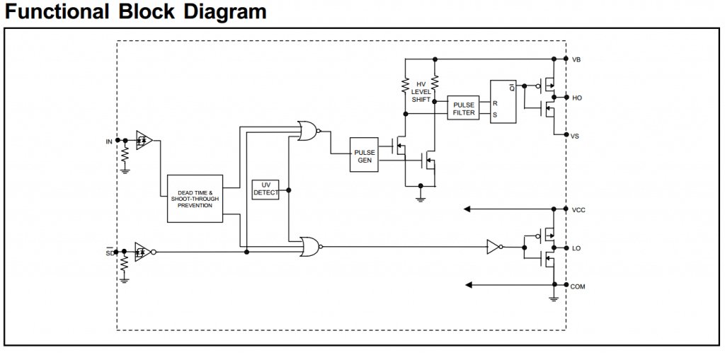
The IR2104(S) are high voltage, high-speed power MOSFET and IGBT drivers with dependent high and low side referenced output channels. Proprietary HVIC and latch-immune CMOS technologies enable ruggedized monolithic construction. The logic input is compatible with standard CMOS or LSTTL output, down to 3.3V logic. The output drivers feature a high pulse current buffer stage designed for minimum driver cross-conduction. The floating channel can be used to drive an N-channel power MOSFET or IGBT in the high-side configuration, which
operates from 10 to 600 volts.
Connection diagram:
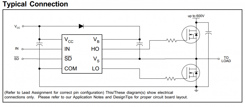
In IR2104, the input signal is given to the INPUT (Pin#2) of the IC. An active-low signal at the SD pin stops the output from driving. A bootstrap capacitor of 0.1uF works fine, but this capacitor must be of the best quality (low ESR).
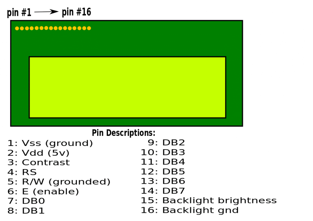
Visualization of information:
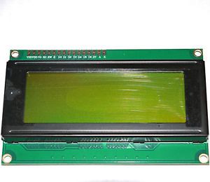
For visualization, a very common device is an LCD. In this project, we’ll use a 20×4 LCD to visualize information. Besides, LEDs are used to indicate the mode of operation.
This LCD needs 6 pins for communication and the pin diagram of the LCD is:
Bluetooth data logging:
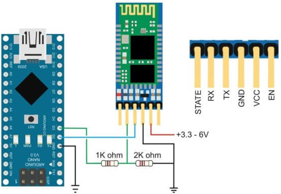
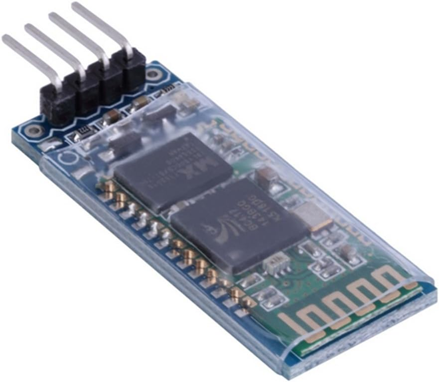
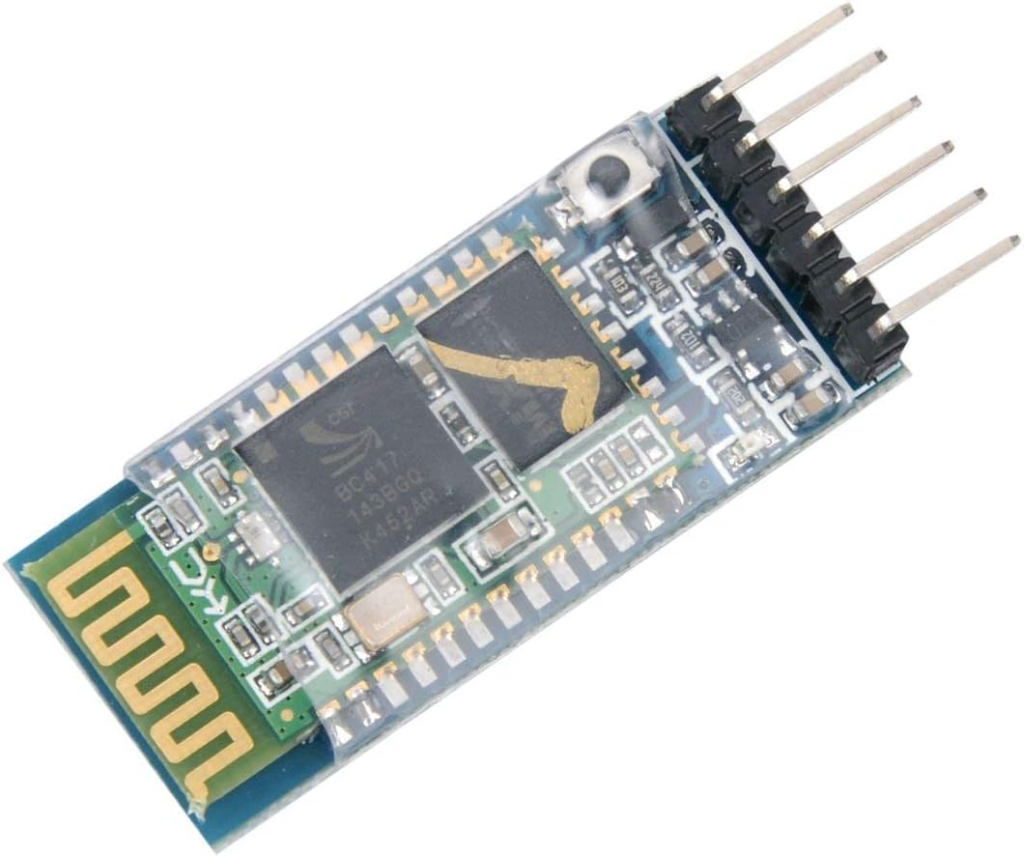
For remote data logging, a Bluetooth module is used here. Although memory cards are used in most commercial devices as field data loggers, in this project, we are not logging data locally. We kept an option to monitor the charge controller data remotely. That is why a Bluetooth module HC06 is used.
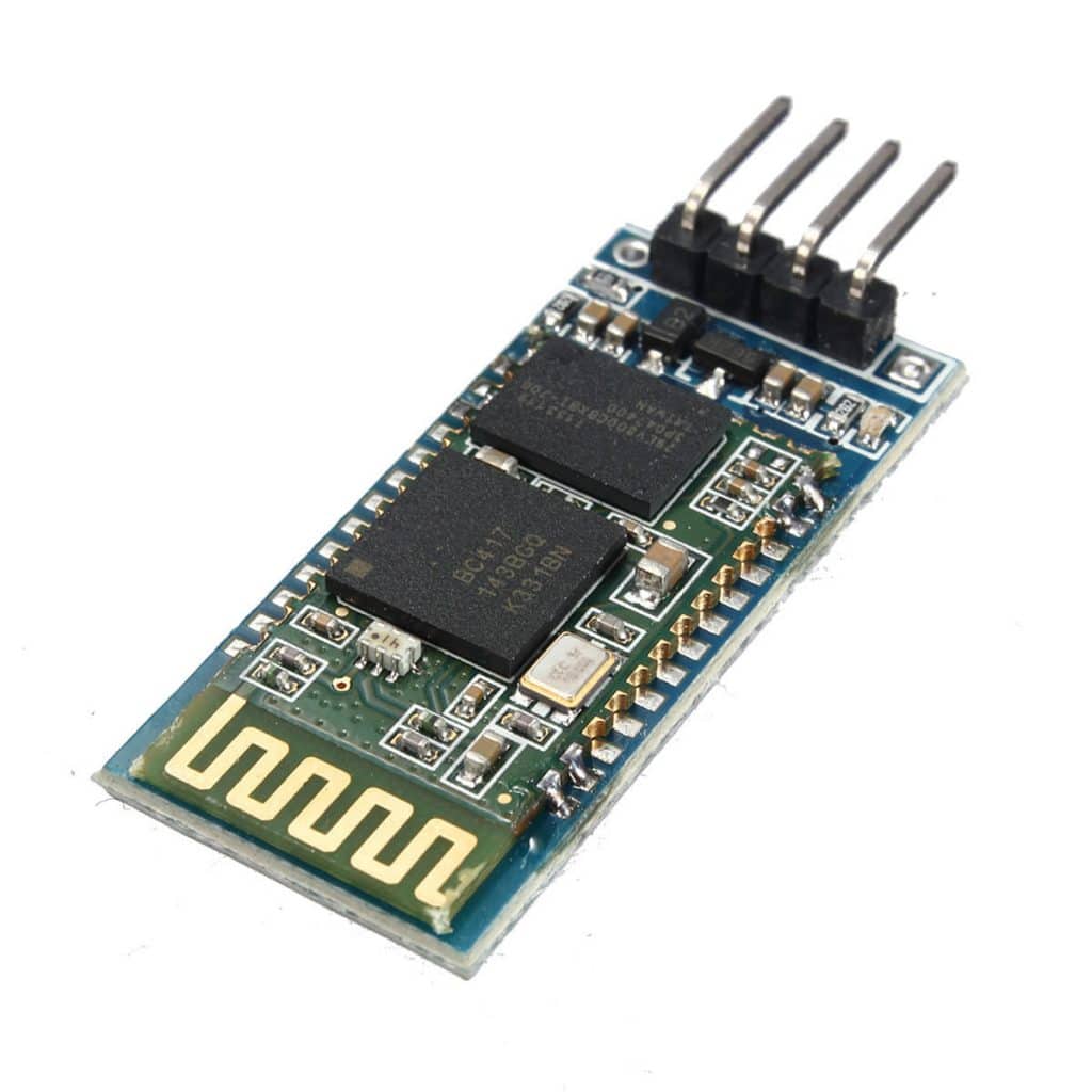
This is a very common Bluetooth module. Simple connection through the UART module of the microcontroller. It can be connected with an Android cell phone, and an app on the phone can be used to monitor and log the data.
SMPS mobile charging:
A mobile charge was not so important as part of an MPPT solar charge controller, but was kept in the design to make the project more useful and interesting. Here, a Switch Mode Power Supply circuit is designed with the MC34063A IC, which can supply 5V at 350mA very easily. The circuit diagram for our mobile charger is:

You can download the datasheet for MC34063A from here.
Read more:
- DC/DC converter using Transistors
- Buck converter using NE555 and N-Channel MOSFET
- BUCK converter using low-side N-Channel MOSFET
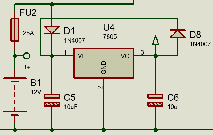
Power supply for circuit parts:
There are microcontrollers, ACS current sensors, Bluetooth modules, and LCDs, all these devices need power to run. All these components need a 5V DC supply. This power supply is designed with an LM7805 voltage regulator IC. The circuit diagram is:
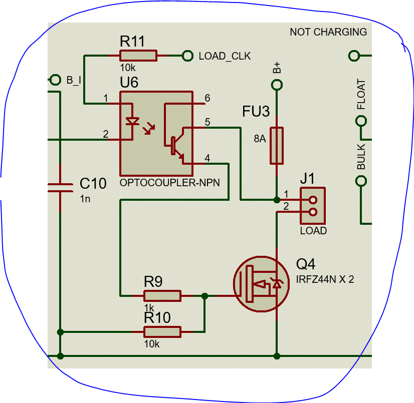
Load control unit:
Although most of the MPPT solar charge controllers don’t have a load control unit, in our project we kept this part. Loads are supplied from our battery and switched by a MOSFET. A gate driver (Opto-coupler: P817C) is introduced as well to drive the MOSFET gate.
Combining all together:
So our MPPT solar charge controller has various parts that work in combination. If we shortlist again, we can make this:
- A DC/DC buck converter: Synchronous Buck Converter
- Gate driving circuit: IR2104
- Protecting Circuit: Fuse + Diode(MOSFET)
- Load control circuit: MOSFET & Gate driver
- Data-logging circuit: Bluetooth Module (HC06)
- Sensing circuit: ACS712-30 & resistors
- Power supply circuit: LM7805 circuit
- Mobile charge circuit: MC34063A circuit
- 5 Must-Try ESP32 Projects for Beginners (2025 Edition)
Block diagram:
The Block Diagram of our project is:

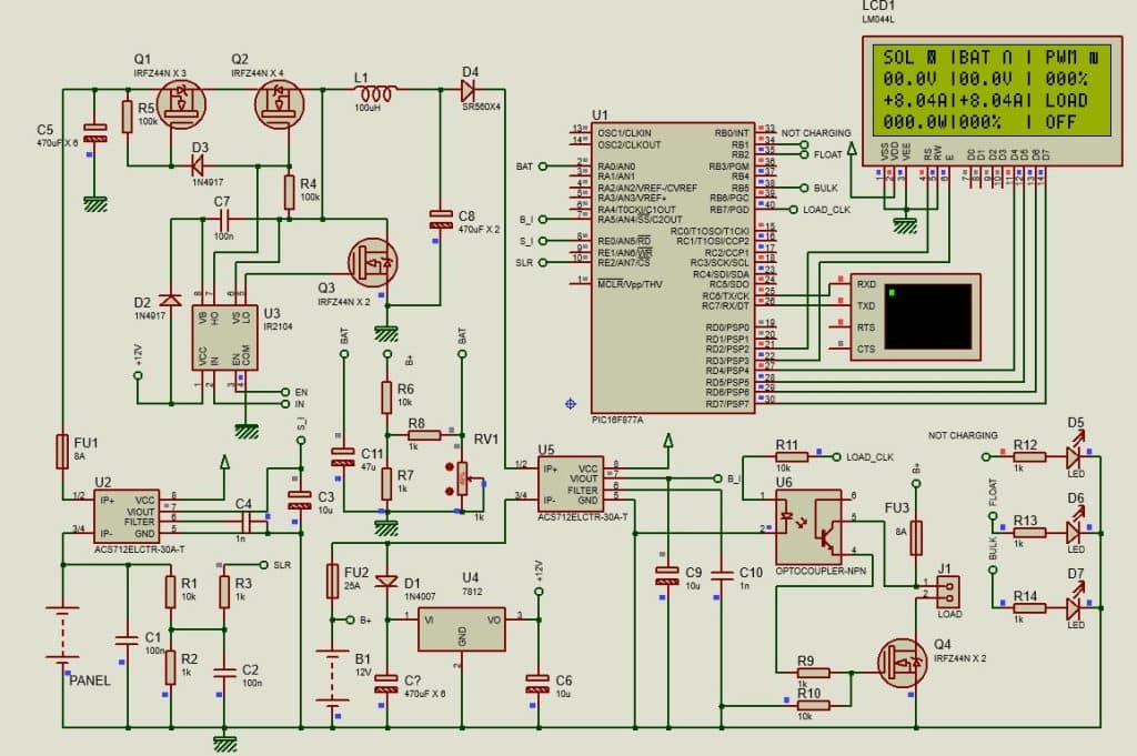
Circuit Diagram:
Here is the circuit diagram of this project:
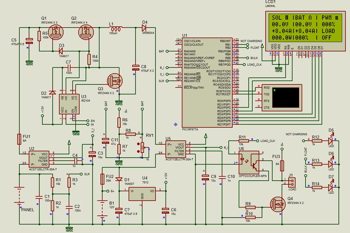
As this is a big power circuit, Proteus is unsuitable for simulation. The error in the simulation is very common in this type of big project.
You can download the Proteus file from here.
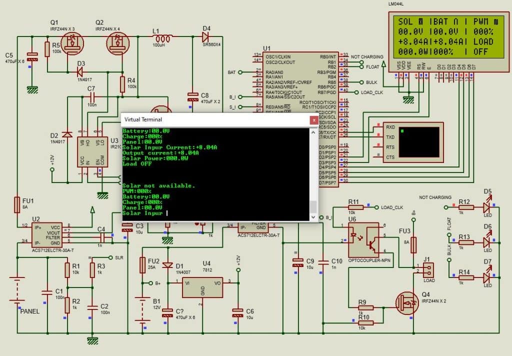
Simulation Result:
Coding:
I bought the MikroC license in 2014 as I work professionally. So all of my projects based on PIC microcontrollers are programmed using this compiler. Here is the mikroC code for this project.
/*******************************************************************************
*     Program for, "MPPT Solar Charge Controller using Sync. Buck converter"   *
*                  Program Written by_ Engr. Mithun K. Das                     *
*                         MCU: PIC16F877A; X-Tal:8MHz                          *
*                               Date:17-01-2016                                *
*******************************************************************************/
// LCD module connections
sbit LCD_RS at RD2_bit;
sbit LCD_EN at RD3_bit;
sbit LCD_D4 at RD4_bit;
sbit LCD_D5 at RD5_bit;
sbit LCD_D6 at RD6_bit;
sbit LCD_D7 at RD7_bit;

sbit LCD_RS_Direction at TRISD2_bit;
sbit LCD_EN_Direction at TRISD3_bit;
sbit LCD_D4_Direction at TRISD4_bit;
sbit LCD_D5_Direction at TRISD5_bit;
sbit LCD_D6_Direction at TRISD6_bit;
sbit LCD_D7_Direction at TRISD7_bit;
// End LCD module connections
void Lcd_COut(char row, char col, const char *cptr)
{
  char chr = 0;             //first, it is used as empty string
  Lcd_Out(row, col, &chr);  //nothing to write but set position.
  for ( ; chr = *cptr ; ++cptr ) Lcd_Chr_CP(chr); //out in loop
  asm CLRWDT;
}
void UART_Write_CText(const char *cptr)
{
    char chr;
    for ( ; chr = *cptr ; ++cptr ) UART1_Write(chr);
}
const char character6[] = {0,29,21,21,21,21,23,0};
const char character5[] = {31,21,21,27,27,21,21,31};
const char character4[] = {14,17,17,17,17,17,17,31};
const char character3[] = {14,17,17,17,17,17,31,31};
const char character2[] = {14,17,17,17,17,31,31,31};
const char character1[] = {14,17,17,31,31,31,31,31};
const char character[] = {14,31,31,31,31,31,31,31};
void CustomChar(char pos_row, char pos_char,char num)
{
    char i;
    switch(num)
    {
      case 0:
           {
              Lcd_Cmd(64);
              for (i = 0; i<=7; i++)Lcd_Chr_CP(character[i]);
              Lcd_Cmd(_LCD_RETURN_HOME);
              Lcd_Chr(pos_row, pos_char, num);
            }
      case 1:
           {
              Lcd_Cmd(72);
              for (i = 0; i<=7; i++)Lcd_Chr_CP(character1[i]);
              Lcd_Cmd(_LCD_RETURN_HOME);
              Lcd_Chr(pos_row, pos_char, num);
           }
      case 2:
           {
              Lcd_Cmd(80);
              for (i = 0; i<=7; i++)Lcd_Chr_CP(character2[i]);
              Lcd_Cmd(_LCD_RETURN_HOME);
              Lcd_Chr(pos_row, pos_char, num);
           }
      case 3:
           {
              Lcd_Cmd(88);
              for (i = 0; i<=7; i++)Lcd_Chr_CP(character3[i]);
              Lcd_Cmd(_LCD_RETURN_HOME);
              Lcd_Chr(pos_row, pos_char, num);
           }
      case 4:
           {
              Lcd_Cmd(96);
              for (i = 0; i<=7; i++)Lcd_Chr_CP(character4[i]);
              Lcd_Cmd(_LCD_RETURN_HOME);
              Lcd_Chr(pos_row, pos_char, num);
           }
      case 5:
           {
              Lcd_Cmd(104);
              for (i = 0; i<=7; i++)Lcd_Chr_CP(character5[i]);
              Lcd_Cmd(_LCD_RETURN_HOME);
              Lcd_Chr(pos_row, pos_char, num);
           }
      case 6:
           {
              Lcd_Cmd(112);
              for (i = 0; i<=7; i++)Lcd_Chr_CP(character6[i]);
              Lcd_Cmd(_LCD_RETURN_HOME);
              Lcd_Chr(pos_row, pos_char, num);
           }
    }
}
void Background()
{
  Lcd_COut(1,7,"|");Lcd_COut(2,7,"|");Lcd_COut(3,7,"|");Lcd_COut(4,7,"|");
  Lcd_COut(1,14,"|");Lcd_COut(2,14,"|");Lcd_COut(3,14,"|");Lcd_COut(4,14,"|");
  Lcd_COut(1,1,"SOL"); Lcd_COut(1,8,"BAT");Lcd_COut(3,15," LOAD");Lcd_COut(1,15," PWM");
  CustomChar(1,12,0);// Battery
  CustomChar(1,5,5);// Panel
  CustomChar(1,20,6);// PWM
}
long adc_rd=0;
unsigned int Battery=0,Solar=0,i;
unsigned int Battery1=0,Solar1=0;
unsigned int Charging_current=0,Battery_Current=0;
unsigned int Charging_Current1=0,Battery_Current1=0;
unsigned int Solar_Power = 0,Solar_Power1=0;
unsigned int Previous_power=0,Recent_power=0;
unsigned int parcentage=0,parcentage1=0;
int duty=0,duty1=0;
int d_prcnt=0,d_prcnt1=0;
short charging_mode=0;//0 = bulk by default
bit load;
void Get_Battery();
void Get_Solar();
void Get_Charging_Current();
void Get_Battery_Current();
void Get_Solar_power();
void Load_Control();
void Charging_Control();

#define    load_clk   RB7_bit
#define    Clock_EN   RC1_bit
#define    Bulk_LED   RB5_bit
#define    Float_LED  RB2_bit
#define    NoChar_LED RB1_bit
#define    ON         1
#define    OFF        0
short charge = 0;
unsigned int chr_cnt=0;
void main()
{
 TRISA = 0xFF;//all input
 TRISE0_bit = 1;//set as input
 TRISE2_bit = 1;//set as input
 TRISC = 0x00;//all output
 TRISB = 0x00;//all output
 ADCON1 = 0x00;//all Analog ing
 Delay_ms(100);
 Lcd_Init();//initialize LCD
 Lcd_Cmd(_LCD_CLEAR);//clear display
 Lcd_Cmd(_LCD_CURSOR_OFF);//cursor off
 Lcd_COut(1,1,"MPPT Solar Charger");
 PWM1_Init(22500);// initialize PWM at 22.5 KHz
 PWM1_Start();//start PWM
 PWM1_Set_Duty(duty);// duty cycle = (duty/255) X 100 %
 UART1_Init(9600);
 Delay_ms(2000);
 Lcd_Cmd(_LCD_CLEAR);//clear display
 Background();
 load = 1;
 OPTION_REG = 0x0F;//enable WDT
 while(1)
 {
    asm CLRWDT;
    Get_Battery();
    Get_Solar();
    Get_Charging_Current();
    Get_Battery_Current();
    Get_Solar_power();
    Load_Control();
    Charging_Control();

 }//while(1)
}//void main

void Charging_Control()
{
    char pwm_prcnt[]="000%";
    if(Solar>125)
    {
       Clock_EN = ON;//enable clock
       NoChar_LED = OFF;

        if(Battery>143)charge = 1;
        if(Battery<136)charge = 0;

        if(charge==1)
        {
            charging_mode = 1;// go to float mode
            Float_LED = ON;
            Bulk_LED = OFF;
            UART_Write_CText("Charging mode: Float \r\n");
            if(Charging_current<50)
            {
               if(duty<254)duty++;
               else duty = 254;
            }
            if(Charging_current>50)
            {
               if(duty>1)duty--;
               else duty = 1;
            }
        }
        if(charge==0)
        {
            charging_mode = 0;
            Float_LED = OFF;
            Bulk_LED = ON;
            UART_Write_CText("Charging mode: Bulk \r\n");

            if(chr_cnt>300)
            {
                 Recent_power = Solar_Power;
                 if(Recent_power>=Previous_power)
                 {
                    if(duty<254)duty+=1;
                 }
                 else
                 {
                    if(duty>30)duty-=1;
                 }
                 Previous_power = Recent_power;
            }
            else
            {
                  if(Solar>145)
                  {
                     if(Battery<140 && Battery_Current<500)
                     {
                        if(duty<244)duty+=10;
                        else duty = 254;
                     }
                     else
                     {
                        if(duty>1)duty--;
                        else duty = 1;
                     }
                  }
                  else if(Solar<Battery)
                  {
                      if(duty>10)duty-=10;
                      else duty = 1;
                  }
                  chr_cnt++;
            }
        }
    }
    else if(Solar<105)
    {
       Clock_EN = OFF;//Disable clock  when Solar not available
       NoChar_LED = ON;
       Float_LED = OFF;
       Bulk_LED = OFF;
       duty = 0;
       UART_Write_CText("Solar not available. \r\n");
       chr_cnt = 0;
    }

    PWM1_Set_Duty(duty);
    d_prcnt = duty*100/255;
    pwm_prcnt[0] = d_prcnt/100 + 48;
    pwm_prcnt[1] = (d_prcnt/10)%10 + 48;
    pwm_prcnt[2] = d_prcnt%10 + 48;
    Lcd_Out(2,16,pwm_prcnt);
    UART_Write_CText("PWM:");

    UART1_Write_Text(pwm_prcnt);
    UART_Write_CText("\r\n");

    asm CLRWDT;
    Delay_ms(2);
}
void Get_Battery() {
    char Bat[] = "00.0V";
    char parcen[] = "000%";
    unsigned int adc_sum = 0; // Use unsigned int for summing ADC readings
    unsigned int parcentage;

    ADCON0 = 0x01; // Select channel 0

    // Average 100 ADC readings more efficiently
    for (unsigned char i = 0; i < 20; i++) {
        adc_sum += ADC_Read(0);
        asm CLRWDT; // Watchdog timer reset should be inside the loop
    }
    unsigned int adc_average = adc_sum / 20;

    // Direct calculation to avoid unnecessary casting
    unsigned int Battery = (unsigned int)(adc_average * 0.644922871516105);

    // Optimized string conversion using integer division and modulo
    Bat[0] = (Battery / 100) + '0';
    Bat[1] = ((Battery % 100) / 10) + '0'; // Corrected modulo operation
    Bat[2] = '.';
    Bat[3] = (Battery % 10) + '0';
    Lcd_Out(2, 8, Bat);

    UART_Write_CText("Battery:");
    UART1_Write_Text(Bat);
    UART_Write_CText("\r\n");

    asm CLRWDT;
    Delay_ms(2);

    // Simplified percentage calculation and boundary checks
    if (Solar > 120) {
        parcentage = (Battery > 116) ? (unsigned int)((Battery - 116) * 3.71) : 0;
    } else {
        parcentage = (Battery > 116) ? (unsigned int)((Battery - 116) * 10) : 0;
    }

    // Use ternary operator for concise boundary checks
    parcentage = (parcentage > 100) ? 100 : (parcentage < 0) ? 0 : parcentage;


    // Optimized string conversion
    parcen[0] = (parcentage / 100) + '0';
    parcen[1] = ((parcentage % 100) / 10) + '0';
    parcen[2] = (parcentage % 10) + '0';
    Lcd_Out(4, 8, parcen);

    UART_Write_CText("Charge:");
    UART1_Write_Text(parcen);
    UART_Write_CText("\r\n");

    asm CLRWDT;
    Delay_ms(2);

    // Simplified battery icon display using switch statement
    switch (parcentage / 25) {
        case 0: CustomChar(1, 12, 4); break; // 0-24%
        case 1: CustomChar(1, 12, 3); break; // 25-49%
        case 2: CustomChar(1, 12, 2); break; // 50-74%
        case 3: CustomChar(1, 12, 1); break; // 75-99%
        default: CustomChar(1, 12, 0); break;//100%
    }
}

void Get_Solar() {
    char Sol[] = "00.0V";
    unsigned int adc_sum = 0;

    ADCON0 = 0x39; // Select channel 7

    // More efficient averaging
    for (unsigned int i = 0; i < 20; i++) {
        adc_sum += ADC_Read(7);
        asm CLRWDT; // Keep watchdog reset inside the loop
    }
    unsigned int adc_average = adc_sum / 20;

    // Direct calculation
    unsigned int Solar = (unsigned int)(adc_average * 0.537634408602151);

    // Optimized string conversion with decimal point insertion and correct modulo
    Sol[0] = (Solar / 100) + '0';
    Sol[1] = ((Solar % 100) / 10) + '0';
    Sol[2] = '.';
    Sol[3] = (Solar % 10) + '0';

    Lcd_Out(2, 1, Sol);

    UART_Write_CText("Panel:");
    UART1_Write_Text(Sol);
    UART_Write_CText("\r\n");

    asm CLRWDT; // Watchdog reset after operations
}


// Common helper function to avoid code duplication
void Get_Current(unsigned char channel, char* curr_str, unsigned int* current_value, unsigned char lcd_col_sign,unsigned char lcd_col_val, const char* uart_text) {
    unsigned int adc_sum = 0;
    unsigned int crnt = 0;

    ADCON0 = (channel << 3) | 0x09; // Select the correct channel (optimized)

    for (unsigned char k = 0; k < 20; k++) {
        for (unsigned char i = 0; i < 20; i++) {
            adc_sum += ADC_Read(channel);
            asm CLRWDT;
        }
        unsigned int adc_average = adc_sum / 20;
        crnt += (unsigned int)(adc_average * 4.78515625); //convert into mV
        adc_sum=0;
    }
    crnt /= 20; //get avg value again
    *current_value = abs((int)crnt - 2500) / 0.66; // Calculate current (in Amps). type casting is important here.

    UART_Write_CText(uart_text);

    if (crnt > 2500) {
        Lcd_COut(3, lcd_col_sign, "-");
        UART_Write_CText("-");
    } else if (crnt < 2500) {
        Lcd_COut(3, lcd_col_sign, "+");
        UART_Write_CText("+");
    } else {
        Lcd_COut(3, lcd_col_sign, " ");
    }

    // Optimized string conversion with decimal point insertion
    curr_str[0] = (*current_value / 100) + '0';
    curr_str[1] = '.';
    curr_str[2] = ((*current_value % 100) / 10) + '0';
    curr_str[3] = (*current_value % 10) + '0';
    curr_str[4] = 'A'; // Add 'A' for Amps

    Lcd_Out(3, lcd_col_val, curr_str);
    UART1_Write_Text(curr_str);
    UART_Write_CText("\r\n");

    asm CLRWDT;
    Delay_ms(2);
}

void Get_Charging_Current() {
    char Ccurr[] = "0.00A";
    Get_Current(5, Ccurr, &Charging_current,1,2, "Solar Input Current:");
}

void Get_Battery_Current() {
    char Bcurr[] = "0.00A";
    Get_Current(4, Bcurr, &Battery_Current,8,9, "Output current:");
}

void Get_Solar_power()
{
   char slpwr[]= "000.0W";
   Solar_Power = Solar*Charging_current/100;
   slpwr[0] = Solar_Power/1000 + 48;
   slpwr[1] = (Solar_Power/100)%10 + 48;
   slpwr[2] = (Solar_Power/10)%10 + 48;
   slpwr[4] = (Solar_Power)%10 + 48;
   Lcd_Out(4,1,slpwr);
   UART_Write_CText("Solar Power:");
   UART1_Write_Text(slpwr);
   UART_Write_CText("\r\n");
   asm CLRWDT;
   Delay_ms(2);
}

void Load_Control()
{
   if(Battery>126)load=1;//battery is over 12.6V
   if(Battery<116)load = 0;

   // load control
   if(load)
   {
      load_clk = ON;
      Lcd_COut(4,15," ON ");
      UART_Write_CText("Load ON");
      UART_Write_CText("\r\n");
   }
   else
   {
      load_clk = OFF;
      Lcd_COut(4,15," OFF");
      UART_Write_CText("Load OFF");
      UART_Write_CText("\r\n");
   }
   UART_Write_CText("\r\n");
   UART_Write_CText("\r\n");
   UART_Write_CText("\r\n");
}
//End
You can get the complete project files from here.
Note:
Here in this MPPT solar charge controller, I used the Perturbation and Observation (P&O) algorithm. This is an educational open-source project for learning purposes only. I’ve professional designs, where I use different algorithms as well as have other facilities. You can contact me for professional help on this issue.
PCB designing:
Here is the PCB design of this project.

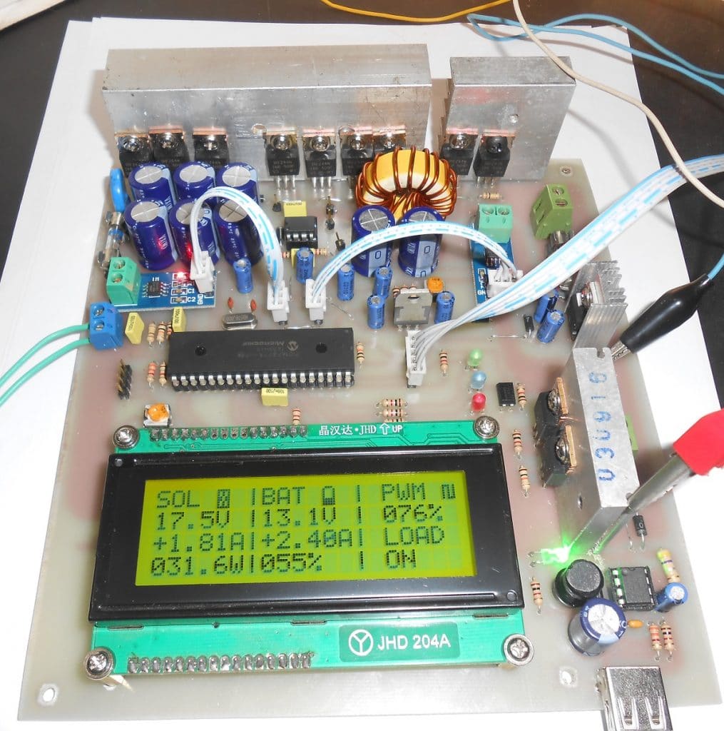
Testing the project in real life:
I made the project for practical testing. Here is the lab test result:

If you want to test making your own, either you can design in your way or use mine from here.
About the field test result:
I gave this MPPT solar charge controller to one of my students who is using this charge controller in his home solar power system. Hopefully, the device is still running.
Mejor component list for this project:
Here is a list of the major components that are used in this project. You can buy these components from amazon.com
- 20×4 LCD
- PIC16F877A micro-controller
- ACS712-30A Hall effect current sensor
- HC06 Bluetooth module
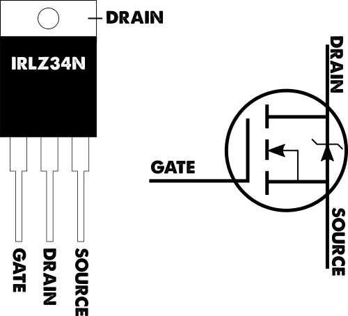
- IRFZ44N MOSFET
- IR2104 synchronous buck converter gate driver
- Inductor coil
Conclusion:
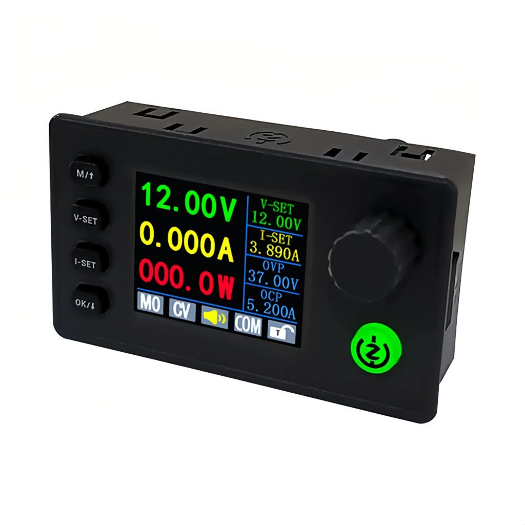
In the end, I hope you come this far. As it was a big project, I omitted some theory parts that you should learn yourself. If I miss some important parts, please let me know. I’ll add that later on. If you still think you are not capable of making one for yourself, but need one to use, then you can buy ready products from the link below:

If you have any questions, feel free to comment below. Thank you for reading the article. For more useful articles, don’t forget to subscribe. Have a good day!
I design similar products; if you need help, feel free to contact me. Thank you!
Liked this article? Subscribe to our newsletter:
or,
Visit LabProjectsBD.com for more inspiring projects and tutorials.
Thank you!

60 Comments
Sagheer Ahmad · 25/01/2021 at 4:28 pm
WILL THIS SOLAR Controller PCB board Operate charging at 24V volts. and I am a resident of Pakistan.
IN4917 is not available in Pakistan.what will be its replacement part?
Thank best Regard
Sagheer Ahmad
Mithun K. Das · 28/01/2021 at 5:12 am
Yes, But you need to configure the regulators first. If 1N4917 is not available then use equivalent.
prasad rao bhupati · 04/03/2023 at 2:19 am
sir i want mppt solar charger detail components list
MKDas · 04/03/2023 at 11:52 am
read the full article. you’ll find them.
Godwin · 26/02/2021 at 8:49 pm
Please,I need the professional type that can handle 12,24 and 48v solar panel and upto 40amp
Mithun K. Das · 27/02/2021 at 5:09 am
In that case you can get a product design from our admin. Kindly email him to [email protected] Thanks.
prabhash kumar · 07/04/2021 at 4:29 pm
Please share 24volt input DC to dc boost converter ..with code..gain good knowledge.. good job
ROBERT · 09/05/2021 at 7:33 pm
sir please can u increase the current to up to 50amps. I try to increase it but not working for me and from the one provided it can increase to even 10amp. please help
MKDas · 10/05/2021 at 5:29 am
This design is not suitable for high amp. You need to convert it into N-Channel low side MOSFET type switching for high amp. See another article on low side MOSFET based buck converter on my blog.
Zahid · 10/05/2021 at 4:11 am
In the display the power shows maximum 65W, but current & voltage shows correctly, after 65w it shows 000W, please suggest me how to solve the problem.
MKDas · 10/05/2021 at 5:29 am
check the program, display power subfunction.
Zahid · 13/05/2021 at 3:41 am
I tried but didn’t succeed, please tell me which line i have change. I’m not expert in coding.
MKDas · 13/05/2021 at 11:23 am
Set Solar_Power as long. hope it works.
max · 03/06/2021 at 11:38 am
Dear sir
Can I use 1N4148 instead of 1N4917 .
Regards
MKDas · 03/06/2021 at 11:51 am
Check the datasheet of IR2104. 1N4148 works fine.
max · 05/06/2021 at 12:40 am
thank you so much sir
riahi baha · 16/06/2021 at 12:43 pm
what are the material reference used in this model ??
MKDas · 16/06/2021 at 1:02 pm
Kindly clarify what you are trying to express.
Joseph Oyewale · 27/09/2021 at 3:33 am
Thanks for sharing this, sir what is the range of solar panel input voltage to this charge controller design above
MKDas · 28/09/2021 at 5:11 pm
36V max
Kankie Allen · 16/01/2022 at 5:14 pm
Can i please get the necessary calculations for the capacitors inductors and resistors
MKDas · 16/01/2022 at 5:44 pm
Most of the calculations are given in clue or calculator.
David A · 26/01/2022 at 5:40 am
In the first MPPT Charge controller 1 picture, the LCD seems to show 103.35% efficiency (magic!) What conversion efficiency did you actually achieve?
MKDas · 26/01/2022 at 4:34 pm
As every piece of information is not being printed in the LCD at the same time, a minor information gap may happen and that image may be taken at that right moment. Besides, every component has a tolerance. So minor errors can be found very easily. You make one using the concept and make that 100% error-free. That will sound good.
Allen Kankie · 16/03/2022 at 3:04 am
For Q1 Q2 and Q3 why were multiple mosfets used and can it work with a different type pf battery
MKDas · 16/03/2022 at 11:37 am
Multiple MOSFETs to gain current capacity and share load and heat. For different types of batteries, just adjust charging level and cutoffs.
G K · 23/11/2024 at 7:44 am
Nonsense. Q1, Q2 & Q3 do NOT “share the load”. There is no current gain by using all three.
MKDas · 25/11/2024 at 12:07 pm
Q1 is used as a Diode, Q2 as the upper switch and Q3 as the Sync. Switch. You should study on Synchronous buck converter first Mr.
Kakama Mark · 31/03/2022 at 5:41 pm
What are the alternatives for the schottky sr580.
What are the consequences of only using one single mosfet, Schottky and capacitor at Q1 Q2 Q3 and d4 C? And C8
MKDas · 02/04/2022 at 12:57 pm
First, Google is always open to searching the alternatives.
second, you can use single power devices, but if you use two 5A switches rather than one 10A, the heat dissipation as well as safety factor increase. That is why, we try to use more than one if necessary in power switching purpose.
Kakama Mark · 24/06/2022 at 5:33 pm
In the code and the proteus circuitnthe mosfet pins IN and SD are defined or connected what could the connections. If SD rc1 what is the PWM signal pin
MKDas · 24/06/2022 at 9:05 pm
RC2/CCP1
ojie · 06/09/2022 at 9:48 pm
Thank you so much for this build. I have been able to study and trace your pcb to know how you made use of multiple mosfet. Which line(s) of code do I need to change to increase the charging level and cutoff for use with 24v battery (increase the charging current to like 50amps. )
MKDas · 07/09/2022 at 4:10 pm
yes, study on it and learn. Also try changing if you want. thanks.
Samin Zawad · 12/02/2023 at 10:40 pm
Sir,
is it possible to implement the same project in arduino uno ?
What are the changes required in code and schematics for that?
MKDas · 14/02/2023 at 11:47 am
First, understand the concept. Then you can use almost any microcontroller.
Walter Meurat · 04/03/2023 at 3:37 am
I read your article with great satisfaction.
Thank you very much for sharing your knowledge, I hope this helps readers to motivate them to investigate
Greetings from Argentina
MKDas · 04/03/2023 at 11:52 am
thanks
Anandhu · 22/08/2023 at 11:54 pm
Pcb design & Gerber file please
MKDas · 04/09/2023 at 8:29 pm
will fix the link soon.
Paul · 10/01/2024 at 2:42 am
Please what is the maximum output current of this design?
MKDas · 10/01/2024 at 12:04 pm
10A
Hamza · 23/03/2024 at 4:28 pm
Tell me the replacement of sr560
MKDas · 23/03/2024 at 7:41 pm
Google
Hamza · 25/03/2024 at 6:24 am
Can we you use same circuit for 24v battery connection or panel supply?
MKDas · 25/03/2024 at 12:11 pm
maintain the ratio.
Hamza · 25/03/2024 at 6:25 pm
Tell me the range of Battery and panel to mantain the ratio to what extend in current circuit without changing a single component
MKDas · 25/03/2024 at 8:42 pm
First learn it, try to learn the concept of working. once you understand it well, then you can change the circuit or code for any different ranges. But if I keep mentioning where to change or what to do, it will be keep going forever. And I do not have that much time to teach you individually. So kindly try to capture the knowledge of the project. then use it as per your requirement.
ihsan · 24/06/2024 at 9:22 am
this design not working. where output battery voltage stabilized ? this is charging the battery with maximum voltage which is not good for battery life. what you say about this. if i am wrong then guide me so i will learn.
MKDas · 24/06/2024 at 10:46 am
If you measure the output voltage without connecting the battery then yes it must give unregulated voltage which can be higher to the battery voltage. If the converter can’t give extra voltage than the battery, it can not charge the battery. So measure with battery connection.
G K · 23/11/2024 at 7:48 am
Looks like the schematic is wrong. Q3 is not wired correctly. What else is wrong?
MKDas · 25/11/2024 at 12:05 pm
Hello Mr. You have not understood the buck converter configuration yet.
G K · 25/11/2024 at 11:06 pm
Actually, I do understand the Buck Converter. Take a good look at Q3 in your schematic diagram, again. This time without the condescending attitude. You should clearly see that Q3 is incorrectly, shorting out Capacitor C8. That is 100% wrong!!! The DRAIN of Q3 is connected to the wrong side of L1. Now … you can apologize for insulting my intelligence.
MKDas · 26/11/2024 at 12:28 pm
Ah! It’s my mistake while drawing the diagram. I’ll fix it. Thank you for your intelligence.
AndrewK · 30/11/2025 at 4:04 am
Dear MKDas! How can I download the PCB, for example in PDF, so that I only have to iron it?
MKDas · 30/11/2025 at 4:12 pm
there should be an option for that.
AndrewK · 13/12/2025 at 6:09 pm
Can I order the PCB from you?
MKDas · 13/12/2025 at 8:27 pm
Not really but your can get the design from me.
masseur · 26/02/2026 at 11:30 am
Good morning. The file does not compile in microC. It shows an error. Please attach the HEX file.
MKDas · 11/03/2026 at 12:31 pm
whatsapp me