In this article, we are going to see how we can store String in the EEPROM of a microcontroller and recall those strings to print on display or use it for different purposes. Usually, we use ROM as the main memory and RAM for variables. But this technique will save you enough space for those and will allow you to utilize the MCU at the maximum point.
⚠️Disclaimer:
Working with electricity involves serious risk. Ensure you have the necessary skills and take proper safety precautions before attempting any electrical projects. Proceed at your own risk — the author assumes no responsibility for any damage, injury, or issues resulting from the use or misuse of the information provided.
All content on this website is original and protected by copyright. Please do not copy or reproduce content without permission. While most of the resources shared here are open-source and freely accessible for your learning and benefit, your respect for our intellectual effort is appreciated.
If you find our tutorials helpful, consider supporting us by purchasing related materials or sharing our work — it helps keep the content flowing.
Need help or have questions? Leave a comment below — the author is always happy to assist!
Table of Contents
Use of sting in microcontrollers:
String or text what you print on the display while working with microcontrollers. It is not an unknown term to you if you work with a microcontroller. I think all most everyone who worked with microcontrollers faced memory limitation problems while working with microcontrollers due to these ASCII variables or strings.
Here is another article on how you can save RAM & ROM in microcontrollers.
Here is another way to save ROM & RAM and utilize the EEPROM for the variables like String. I think 99% of people who work with microcontrollers did not know this tricks. Even I did not know in the beginning although that was around 2011.
Anyway, let’s find it out how we can utilize the EEPROM for our Strings to save on.
Step1: First create your LCD project like the following:
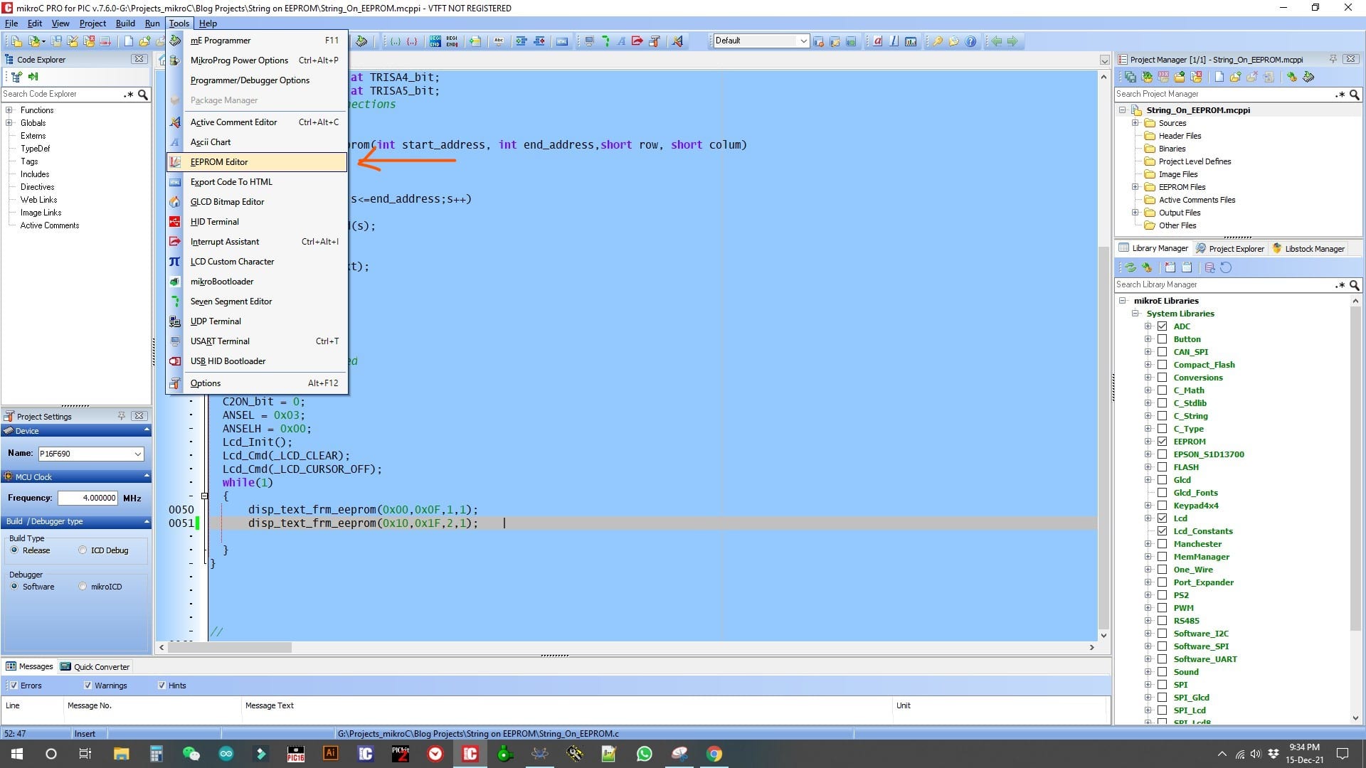
The text format is given below so don’t panic here. After this step go to tools >> EEPROM editor
Then open EEPROM Editor. The window will arrive.
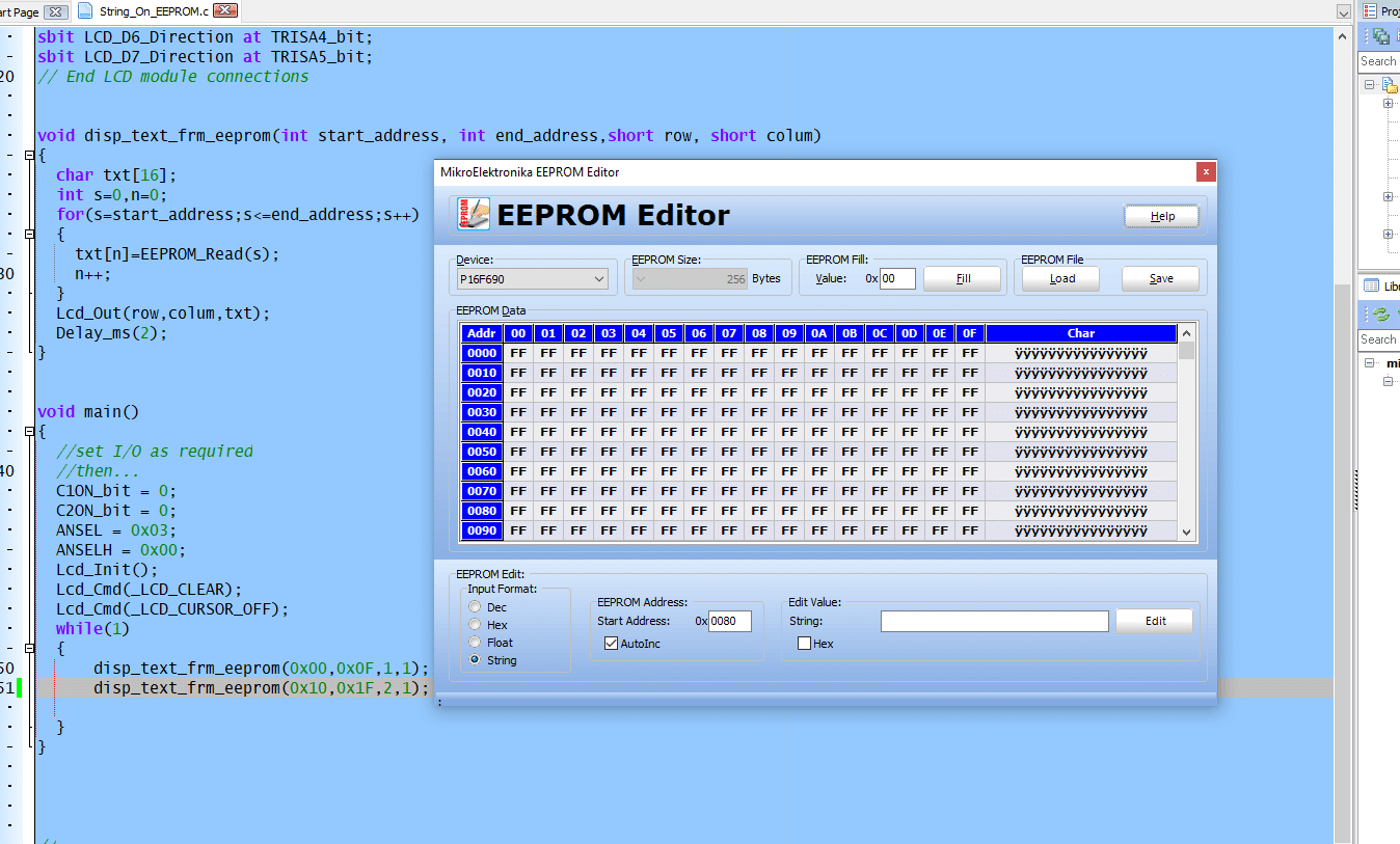
Here is the tool you need to edit. Here, the address starts from 0x00 and increments up to 0xFF depending on EEPROM size. But remember these are all 16 bits per line. 0x00 to 0x0F, then 0x10 to 0x1F and so on. Now, you need to edit the text you need.
Click on the EEPROM input Format >> select String. Then set the address to 0000. Then in the next space write your text like this:
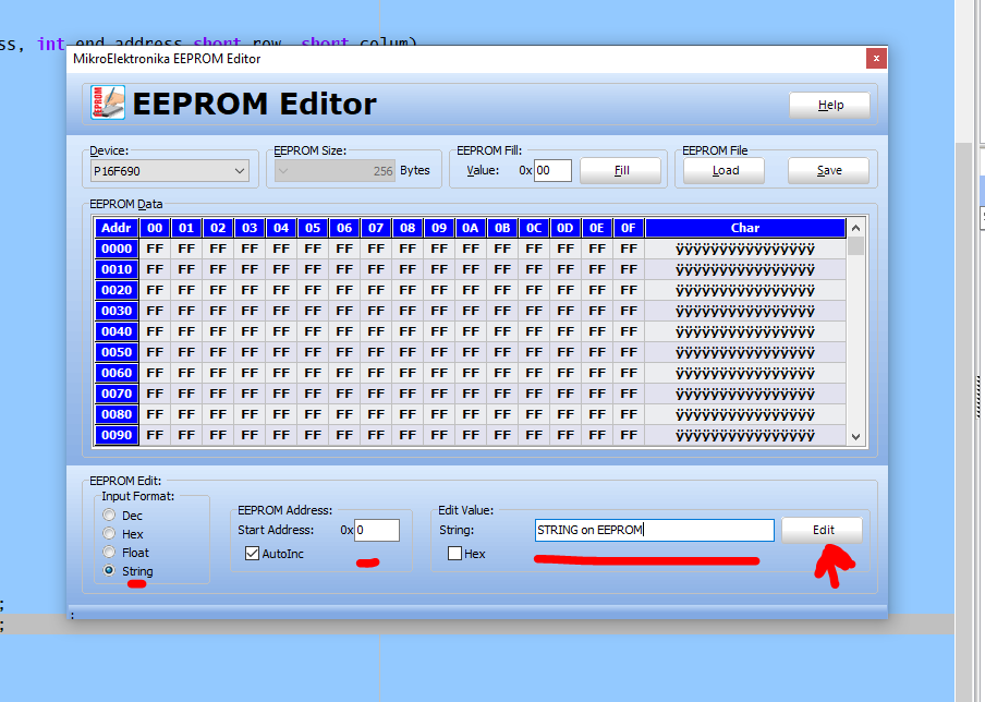
Now click on the Edit button.
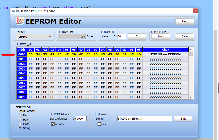
Now click on the Save on the right top corner. Overnight if required. Now build the hex in mikroC.
Step 2: testing on simulator:
This editor generates a .ihex file. But if you simulate with Proteus ISIS then you’ll need the bin file. So rename the file into a binary file, .bin. Then open with proteus.
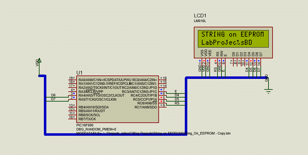
Now the text or string that we stored in the EEPROM is on the LCD. Also, check the used RAM & ROM, surprisingly it consumed only a few %. use more of the function disp_text_frm_eeprom(), this % will increase a little only.
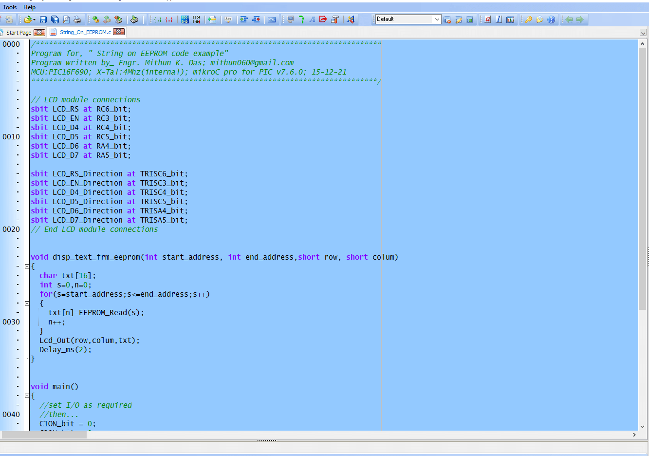
mikroC code:
Here is the mikroC file in text format. You can use this function for your code.
/*******************************************************************************
Program for, " String on EEPROM code example"
Program written by_ Engr. Mithun K. Das; [email protected]
MCU:PIC16F690; X-Tal:4Mhz(internal); mikroC pro for PIC v7.6.0; 15-12-21
*******************************************************************************/

// LCD module connections
sbit LCD_RS at RC6_bit;
sbit LCD_EN at RC3_bit;
sbit LCD_D4 at RC4_bit;
sbit LCD_D5 at RC5_bit;
sbit LCD_D6 at RA4_bit;
sbit LCD_D7 at RA5_bit;

sbit LCD_RS_Direction at TRISC6_bit;
sbit LCD_EN_Direction at TRISC3_bit;
sbit LCD_D4_Direction at TRISC4_bit;
sbit LCD_D5_Direction at TRISC5_bit;
sbit LCD_D6_Direction at TRISA4_bit;
sbit LCD_D7_Direction at TRISA5_bit;
// End LCD module connections


void disp_text_frm_eeprom(int start_address, int end_address,short row, short colum)
{
  char txt[16];
  int s=0,n=0;
  for(s=start_address;s<=end_address;s++)
  {
    txt[n]=EEPROM_Read(s);
    n++;
  }
  Lcd_Out(row,colum,txt);
  Delay_ms(2);
}


void main()
{
  //set I/O as required
  //then...
  C1ON_bit = 0;
  C2ON_bit = 0;
  ANSEL = 0x03;
  ANSELH = 0x00;
  Lcd_Init();
  Lcd_Cmd(_LCD_CLEAR);
  Lcd_Cmd(_LCD_CURSOR_OFF);
  while(1)
  {
      disp_text_frm_eeprom(0x00,0x0F,1,1);
      disp_text_frm_eeprom(0x10,0x1F,2,1);

  }
}


//
Video:
Here in this video, everything was described. You can check this too.
Conclusion:
I think this article will surprise you. Use the maximum of your microcontroller. If you think this article helps you don’t forget to subscribe for the next one. Thanks.
Liked this article? Subscribe to our newsletter:
or,
Visit LabProjectsBD.com for more inspiring projects and tutorials.
Thank you!
You may check this too:
- Interfacing External EEPROM with PIC microcontroller
- Make an MPPT Solar charge Controller with Synchronous Buck Converter
- Pure sine wave inverter using PIC16F76
- Arduino based egg incubator
- How to make an AC dimmer with PIC12F675 and TRIAC
- Make a simple Data-Logger with Arduino UNO for your solar power plant
- Solar Charge Controller circuit & working principle of ON/OFF charge controller
- A smart Battery charger circuit design guide
- Get long life of your Lead-Acid battery by selecting the right charging method
- Electronic Component Tester


3 Comments
Md. Yousuf Molla · 16/12/2021 at 9:22 pm
This post is very helpful for me.
Many many thanks, Sir.
R K Hamy · 08/01/2022 at 3:46 pm
Very useful article.
Many Thanks.
Emmytexy · 01/04/2022 at 10:41 am
I love your lecturing every educative