A dimmer circuit is one of the basic circuits in power electronics that people want to make. In this article, let’s learn how to make an AC dimmer circuit. In this project, we will use a PIC 12F675 microcontroller and a TRIAC as the switching device. Let’s start our AC dimmer with a PIC 12F675 microcontroller.
⚠️Disclaimer:
Working with electricity involves serious risk. Ensure you have the necessary skills and take proper safety precautions before attempting any electrical projects. Proceed at your own risk — the author assumes no responsibility for any damage, injury, or issues resulting from the use or misuse of the information provided.
All content on this website is original and protected by copyright. Please do not copy or reproduce content without permission. While most of the resources shared here are open-source and freely accessible for your learning and benefit, your respect for our intellectual effort is appreciated.
If you find our tutorials helpful, consider supporting us by purchasing related materials or sharing our work — it helps keep the content flowing.
Need help or have questions? Leave a comment below — the author is always happy to assist!
Table of Contents
How an AC dimmer circuit works:
There are 3 basic ways to make an AC dimmer with PIC12F675.
- Changing the voltage with VARIAC/variable transformer
- Using PWM signal
- Using TRIAC with firing angle control
You may read this too: Make a soft starter for AC loads
Variable transformer:
Variable transformers are transformers that can put out differing amounts of voltage from the same input voltage. There are trademarked versions of these transformers and there are versions that are simply sold as variable transformers, some of which are built to custom specifications.

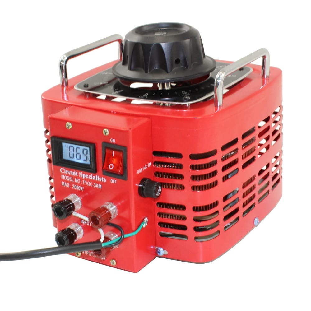
This type of transformer is mostly used in laboratories to change the AC voltage from the fixed input voltage. But using this large device is not a good sign to make a dimmer for a small load. But if the load is large too, sometimes these are the most suitable.
Using PWM signal:
Sometimes, PWM signals are used in AC dimmers but as this signal generates harmonics and EMI, the use of this technique is very few. I’ll discuss this technique in another article.

Using TRIAC with firing angle control:
For the AC dimmer with PIC12F675 circuit, TRIAC or SCRs are the best choices for almost any load. Using a Thyristor makes the circuit small, as well as loss, is very low. In this method, the output is regulated by controlling the firing angle of the Thyristor which generates an AC signal like this in the output load:

That means the firing angle can be controlled from 0-180º to deliver 0-100% to the output. This way, almost any AC load can be dimmed according to this firing angle. Each time we can set a pulse to trigger the thyristor from the zero-crossing point to get the exact amount of output. The working principle will be easier to understand if you see this animated image of firing angle control:
If we want to deliver the full sine wave to the load then we have to use TRIAC and if we want to deliver only the positive half cycle, then we can use SCR. But in that case, the output will be DC rather than AC signal.
You may read this useful article too: Make a soft starter for AC loads
Zero-crossing point:

To know more about zero-crossing: Wiki.
Now, let’s see what a TRIAC is.
TRIAC:
TRIAC is a generic trademark for a three-terminal electronic component that conducts current in either direction when triggered. Its formal name is bidirectional triode thyristor or bilateral triode thyristor._wiki
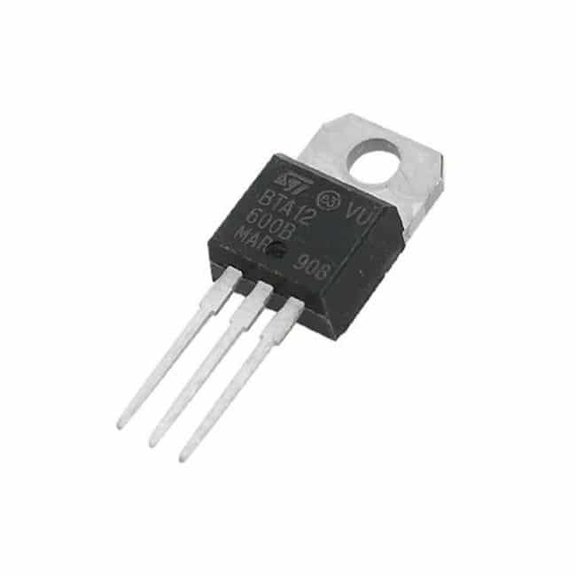
You can imagine this as two anti-parallel SCRs in one device. In SCR, the output is triggered only when the input is positive half and in TRIAC, it can trigger in both ways.
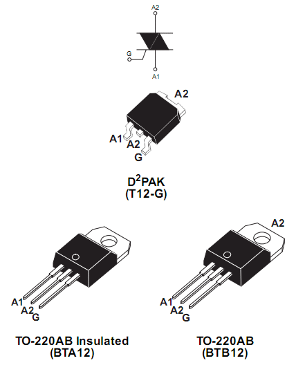
In this project, we will use a very common TRIAC: BTA12.
TRIAC driver:
Only using a TRIAC will not solve everything. We have to use a driver for this TRIAC. Yes, we can drive using different ways, but using an Opto-coupler will be the best way to drive.
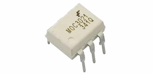
We can use MOC3021 for this purpose in our AC dimmer with PIC12F675.
Now, we have a TRIAC and a driver for this TRIAC. But what else we need? Yes, we need to find the zero-crossing point of each cycle of the sine wave. That is why we need a zero-crossing circuit.
Zero-crossing circuit:
There are lots of ways to design this circuit. But I like using a transistor to make it simple. As with most of the circuits, we use transformers so we can detect the zero-crossing point easily using this circuit:

But in practice, I use this concept and modified my circuit in my ways.
Circuit diagram:
Here is the circuit diagram for AC dimmer with PIC12F675:
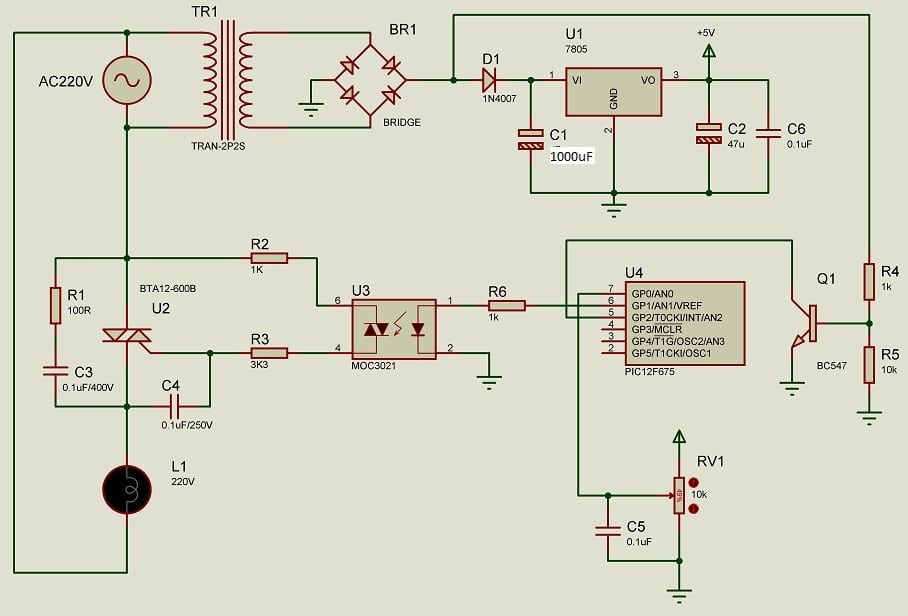
As you can see, I used only two resistors and a transistor, and an extra diode to make the zero-crossing circuit.
The other part of the circuit is not so complex at all. The gate driver circuit is a very easy one. Although the datasheet provides different values, after doing more practical works I changed the values which work excellent.
A resistor (100Ω) and a capacitor (0.1µF/400V) in series which is connected in parallel with TRIAC’s MT1 and MT2 pin is a snubber circuit. Snubbers are energy-absorbing circuits used to suppress the voltage spikes caused by the circuit’s inductance when a switch, electrical or mechanical, opens. The most common snubber circuit is a capacitor, and the resistor connected in series across the switch
snubber circuit is a useful circuit for any switching device. I’ll discuss this later in another article. But for now, take it in a simple way.
Here, we used a POT variable resistor which is used as the tuner to tune the output. And a voltage regulator LM7805 gives us a regulated 5V DC supply to run our microcontroller.
Here, we used a PIC12F675 8-pin microcontroller which is very small and pretty for our project. As there is a weak pull-up option in each pin of this micro-controller so, we used that for our zero-crossing circuit.
How is everything working?
The AC supply line is stepped down by a step-down transformer which is giving us 12V AC. Then using a bridge diode, we made it into a rectified DC signal. From this point, we are detecting the zero-crossing point using a transistor circuit. Then, using a diode 1N4007, this rectified signal is connected to a Capacitor of 1000µF, then a voltage regulator. The regulated 5V is supplied to our MCU.
On the other hand, the AC supply is also supplied to our Load through the TRIAC. A set of circuits forms the TRIAC circuit. An RC snubber and a gate driver circuit are the assisting parts of the TRIAC.
Using the INT hardware interrupt feature of our MCU, the zero-crossing signal is sensed by the MCU. Then a timer interrupt is used to trigger the TRIAC through the Gate driver IC MC3021 keeping a precious timing.
Once the INT is triggered, the triggering signal is zero and the timer interrupt starts. After the timer interrupt, the trigger pin is high for 200µS then the trigger pin is low and the timer interrupt is disabled.
Using this basic concept, the dimmer circuit is working. So all we need to use INT hardware interrupt to detect the zero-crossing point. Then, using a timer interrupt, we will generate a 200uS pulse after a precise time from that zero-crossing point. This delay is our main control variable to control the output firing angle. So we can tune this variable to get our controlled output.
A potentiometer is used, and the voltage is read by the ADC of the microcontroller. From this value, we can set our controlled variable to get the controlled output.
Coding:
This is the mikroC code for our AC dimmer with PIC12F675 circuit. Very simple and easy to understand.
/*******************************************************************************
* Program for, "Simple Dimmer circuit using TRIAC, BTA12 & PIC12F675"          *
* Program Written by_ Engr. Mithun K. Das                                      *
* MCU:PIC12F675; X-Tal: 4MHz (internal); mikroC pro for PIC v7.6.0             *
* Date: 22-06-2020                                                             *
*******************************************************************************/

#define      Trigger     GP1_bit
int TMR_Value = 0;
unsigned int adc_val=0,i=0;

void Interrupt() iv 0x0004 ics ICS_AUTO
{
   if(INTF_bit)//if there is any INT Interrupt
   {
      INTF_bit = 0;
      Trigger = 0;//reset trigger

      TMR0 = TMR_Value;
      TMR0IE_bit = 1;//enable timer
      TMR0IF_bit = 0;//clear flag
   }

   if (TMR0IF_bit)
   {
      TMR0IF_bit = 0;
      Trigger = 1;//set trigger
      Delay_us(200);
      Trigger = 0;
      TMR0IE_bit = 0;//disable timer
   }

}

void main()
{
   TRISIO  = 0b00000101;// GP0 and GP2 as input, GP1 as output
   GPIO=0x00;
   ANSEL=0x11;//AN0 as ADC    with Fosc/8
   ADCON0=0x01; //AN0 activated
   CMCON = 0x07;//comparator off

   GIE_bit=1;// Global Interrupt enable
   PEIE_bit = 1;//periferal INT. enable

   OPTION_REG=0x04;//enable weak-pull-ups
   INTCON         = 0xA0; //Timer0 enable
   TMR0                 = 100;

   INTE_bit = 1;//enable INT Interrupt
   INTF_bit=0;//clear flag
   INTEDG_bit=0;//falling edge

   while(1)
   {
      //read POT
      adc_val=0;
      for(i=0;i<20;i++)
      {
         adc_val+=ADC_Read(0)/4;
      }
      adc_val/=20;

      //filter the values
      if(adc_val>255)adc_val=255;

      //TMR_Value = adc_val;  // this is for direct switching

      //for smooth change
      if(TMR_Value<adc_val)TMR_Value++;
      else if(TMR_Value>adc_val)TMR_Value--;
      Delay_ms(5);

   }//end of while(1)
}//end of void main
Here, I’ve used a timer interrupt to generate a trigger pulse at the right time, starting from each zero-crossing point. And the zero-crossing point is sensed by hardware interrupt INT.
Read more:
- Connect to Raspberry Pi from your Laptop/Desktop using VNC Viewer
- How to reduce noise from DC motor
- Interfacing an external EEPROM with a PIC microcontroller
- Not Enough ROM/RAM error with micro-controllers
Before we test the circuit in the real field, we should test it in simulation. Once it is ok in simulation, we can test the code in real-life circuits.
PCB:
A PCB helps a lot in an electronic circuit to work with. I’ve designed a PCB for our AC dimmer with PIC12F675. Let’s design the PCB:
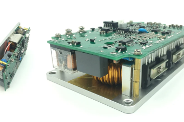
After designing and printing the PCB, this was the result:


Get the project file and PCB files from here. Hex file
Get the Design filesHere, I kept a fuse as a protective device in series with the TRIAC.
Testing with VR-controlled dimmer:
As you can see, the dimmer is working very smoothly, and the waveform is also smooth. Here in my lab, the supply itself is not 100% pure sine wave. Little distortion is there. But it’s not a problem at all.
Dimmer with a button-controlled:
If you want to control the dimming or TRIAC firing angle with a button, then use this circuit:

Here, GP4 & GP5 pins are used for tuning purposes. You can omit the VR RV1 for this case.
Coding with a button:
/*******************************************************************************
* Program for, "Simple Dimmer circuit using TRIAC, BTA12 & PIC12F675"          *
* Program Written by_ Engr. Mithun K. Das                                      *
* MCU:PIC12F675; X-Tal: 4MHz (internal); mikroC pro for PIC v7.6.0             *
* Date: 22-06-2020                                                             *
*******************************************************************************/

#define      Trigger        GP1_bit
#define      High_button    GP4_bit
#define      Low_button     GP5_bit

bit mask1,mask2;
int TMR_Value = 0;
unsigned int adc_val=0,i=0;

void Interrupt() iv 0x0004 ics ICS_AUTO
{
   if(INTF_bit)//if there is any INT Interrupt
   {
      INTF_bit = 0;
      Trigger = 0;//reset trigger

      TMR0 = TMR_Value;
      TMR0IE_bit = 1;//enable timer
      TMR0IF_bit = 0;//clear flag
   }

   if (TMR0IF_bit)
   {
      TMR0IF_bit = 0;
      Trigger = 1;//set trigger
      Delay_us(200);
      Trigger = 0;
      TMR0IE_bit = 0;//disable timer
   }

}

void main()
{
   TRISIO  = 0b00110101;// GP0 and GP2 as input, GP1 as output
   GPIO=0x00;
   ANSEL=0x11;//AN0 as ADC    with Fosc/8
   ADCON0=0x01; //AN0 activated
   CMCON = 0x07;//comparator off

   GIE_bit=1;// Global Interrupt enable
   PEIE_bit = 1;//periferal INT. enable

   OPTION_REG=0x04;//enable weak-pull-ups
   INTCON         = 0xA0; //Timer0 enable
   TMR0                 = 100;

   INTE_bit = 1;//enable INT Interrupt
   INTF_bit=0;//clear flag
   INTEDG_bit=0;//falling edge

   while(1)
   {

      if(!High_button && mask1) //High button is pressed
      {
         mask1=0;//reset mask
         if(TMR_Value<250)TMR_Value+=5;
         Delay_ms(200);
      }
      if(High_button) mask1 = 1;//set mask


      if(Low_button && mask2) //Low button is pressed
      {
         mask2=0;//reset mask
         if(TMR_Value>5)TMR_Value-=5;
         Delay_ms(200);
      }
      if(!Low_button)mask2=1;


   }//end of while(1)
}//end of void main


// for eye friendly
Conclusion:
This AC dimmer with PIC12F675 circuit can be used in AC lamps, Fan motors, etc. Based on load capacity, the TRIAC should be selected. If you use BTA12 in your circuit, it can easily drive up to 500Watts of resistive load and 300Watts of Motor. Keeping a safety factor of 3 is be the best choice for TRIACs because some Transient moments can kill the TRIAC if it can not tolerate it.
I hope this project was helpful to you. If you make one for yourself, it will be a great pleasure for me. Anywhere you need help, let me know. Please share this project and subscribe to my blog. Thank you.
Liked this article? Subscribe to our newsletter:
or,
Visit LabProjectsBD.com for more inspiring projects and tutorials.
Thank you!
Check this out: 5 coolest multimeters you can buy


20 Comments
Chandana · 31/07/2020 at 12:07 am
Excellent Article! Many Thanks For Your Hard Works
CHANDRAMOHAN MOHAN · 25/08/2020 at 5:33 pm
Very Good Work…….sir
Mithun K. Das · 26/08/2020 at 3:17 pm
Thank you
Makeup · 01/11/2020 at 1:59 am
I like the valuable info you provide to your articles. I bookmark your blog and take a look at once more here frequently. I am somewhat certain be informed lots of new stuff proper right here! Good luck for the next!
Mithun K. Das · 01/11/2020 at 2:18 pm
You are welcome
Hairstyles · 03/11/2020 at 2:21 am
Greetings! I know this is kind of off topic but I was wondering which blog platform are you using for this site? I’m getting sick and tired of WordPress because I’ve had problems with hackers and I’m looking at options for another platform. I would be fantastic if you could point me in the direction of a good platform.
Mithun K. Das · 03/11/2020 at 5:47 am
It is WordPress with custom themes and coding.
Joy Majumder · 29/11/2020 at 1:44 pm
Sir please make pic12f675 ir Remote(Fixed Frequency) Control 3 light 1 fan(AC) with button mikro c pro code. I Request .Long time I ti try but fail.
dizi · 09/02/2021 at 10:45 am
Fastidious answers in return of this matter with genuine arguments and explaining all concerning that. Cynthie Rafaello Gratiana Eloisa Walker Yelich
Khademi · 27/06/2021 at 7:29 am
Hi
Thanks for your great project.
I have these problems compiling my code in mikroc compiler
Khademi · 27/06/2021 at 7:30 am
Hi
Thanks for your great project.
I have these problems compiling my code in mikroc compiler
12 401 ; expected, but ‘iv’ found dimmer12f675.c
12 401 ; expected, but ‘0x0004’ found dimmer12f675.c
MKDas · 27/06/2021 at 7:48 am
OK. seems like you missed the line in the void interrupt(). This will be
void Interrupt() iv 0x0004 ics ICS_AUTOThushara · 05/10/2021 at 7:28 am
thank u
Lyubomir · 04/12/2022 at 1:52 am
Many thanks for this useful tutorial, sir.
On the PCB, I see 6 diodes, and 5 on the circuit diagram. What is the 6-th diode for?
MKDas · 05/12/2022 at 11:22 am
Across voltage regulator Out(A) to in(K)
Thushara · 15/09/2023 at 6:45 pm
thank you
Hemantha · 08/08/2024 at 12:01 pm
Dear Sir, I used MOC3041 and BTA16 instead of MOC3021 and BTA12. The Circuit is not working. I checked the voltage at the GP1. It was 0.03-0.05V. I set 2seconds pulse (once) before enable the Global Interrupt , to check the circuit(hardware). The Circuit is working correctly at that 2 seconds. the voltage at the GP1was near 5V. When I change the Trigger time as 3 milliseconds instead of Delay_us(200), the voltage at the GP1 was near 0.5V. And the Circuit is working, but wrong dimming. Please help.
MKDas · 09/08/2024 at 12:11 pm
MOC3041 wont work. Use MOC3021. 41 have internal ZCD which is not aligned with MCU sensing and triggering. So it can’t work properly. everything else in the article is tested ok.
OLanemum · 27/05/2025 at 2:04 am
Hello, I would like to subscribe for this website to take hottest updates, therefore where can i do it please help.
https://tehnoprice.in.ua/shokery-protiv-napadayushchikh-kak-zashchitit-sebya-v-opasnoy-situatsii
https://3dlevsha.com.ua/elektroshoker-svoimi-rukami-vozmozhnost-ili-opasnost-sovety-ekspertov
MKDas · 30/05/2025 at 12:50 pm
just subscribe with email.